CMP Wiring Information

Doing a full page or couple of pages on wiring of CMPs is something that I have tried to do a couple of times, without success. So this time I'm just going to start posting the information.

As back ground all three of my Chevy CMPs had complete or virtually complete original wiring harness giving me a very good starting point. In fact my `45 HUP's harness was in full working condition when I got the truck. All that was needed was to replace some bulbs to get the entire lighting system to work. I drove the HUP for a number of years with the original harness before replacing it with a new one.

Because of War time material restrictions the wire used on CMPs are in most part steel not copper wire, which along with deterioration of the age to the rubber/plastic wire insulation makes replacement a necessity. CMPs were not fitted with what we would call today a fuse or circuit breaker, instead they were fitted with a current limiter a unit that limited current flow to something around 30 Amps. The combination of steel wire, old broken insulation is an invitation for a wiring fire.

Automotive wiring of the day was different from today's, in the first place instead of color coded plastic insulation as used today each wire had a woven covering which had a color trace pattern. Each leg or section of the harness with multiple wires is then covered with a woven cover.

But where do you get a wiring harness for a HUP? My method was to carefully remove the entire harness tagging each lead as it was disconnected. This I mounted on a large plywood board covered with white paper, each section of the harness spread out and mounted on the board with screws and cable ties. Then stapled each individual wire terminal down to the board and printed on the board what it was. I have three of these boards now Pat 13 late HUP, Pat 13 early C60S, and Pat 12 C60L.

Suggestions on making your own harness board

Making your own wiring harness or more exactly copying an original harness is not a difficult job it is just a finicky job that requires attention to detail.

But now to some general comments:

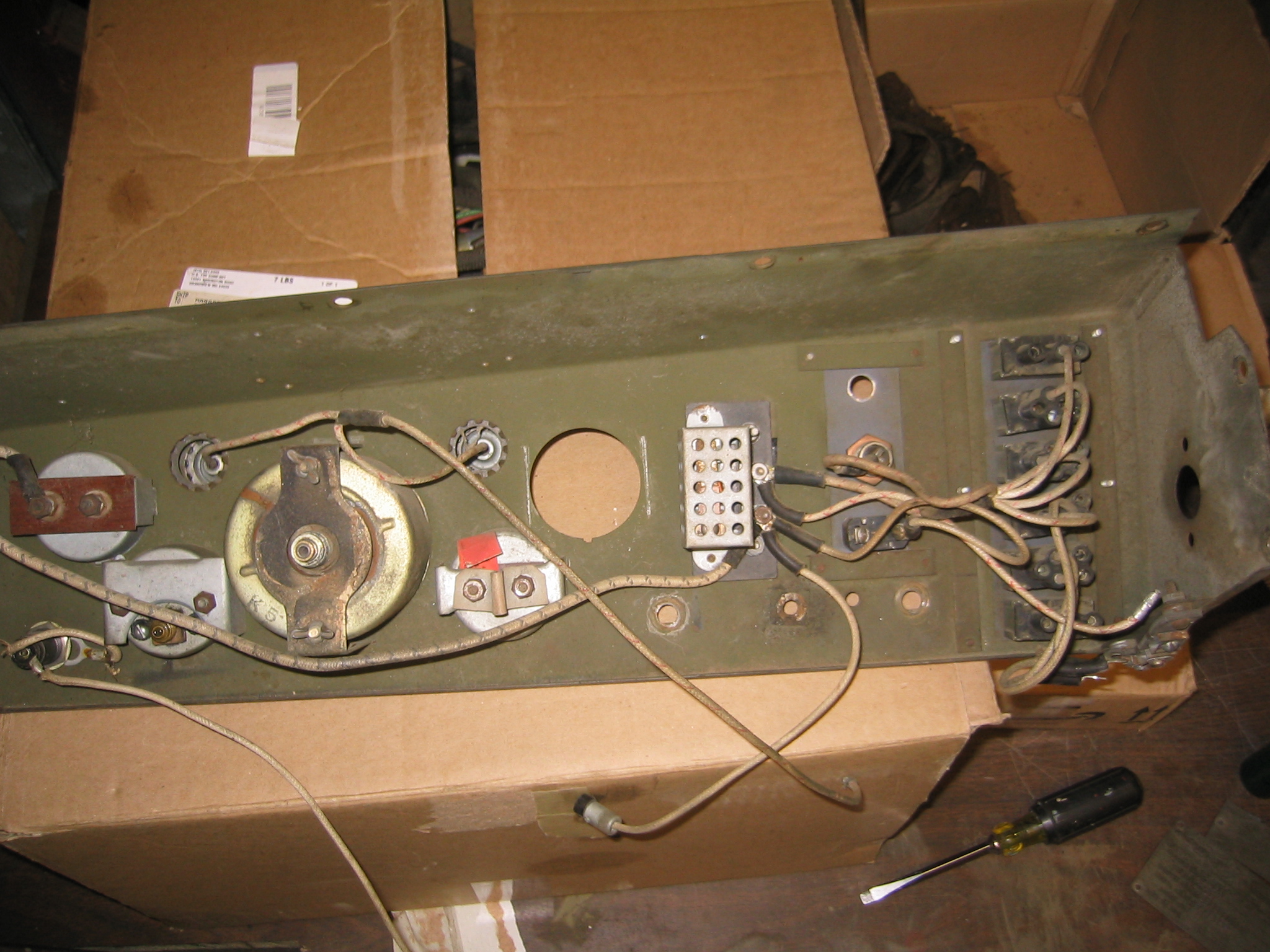
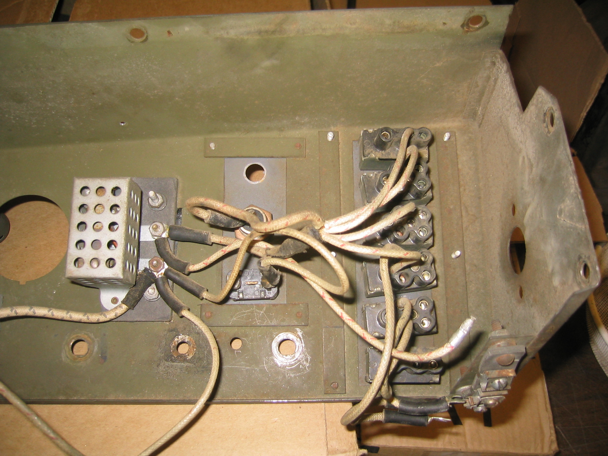
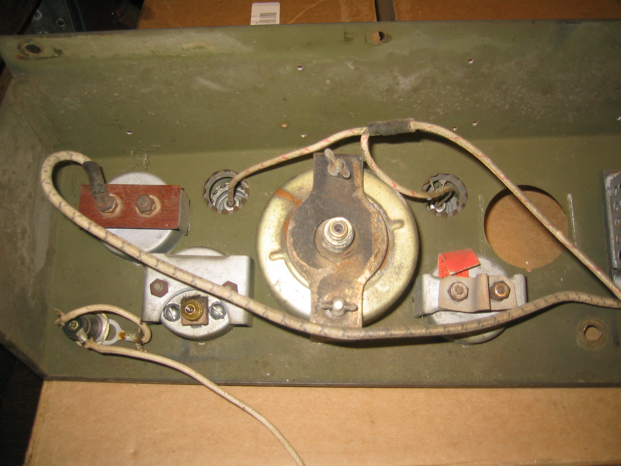
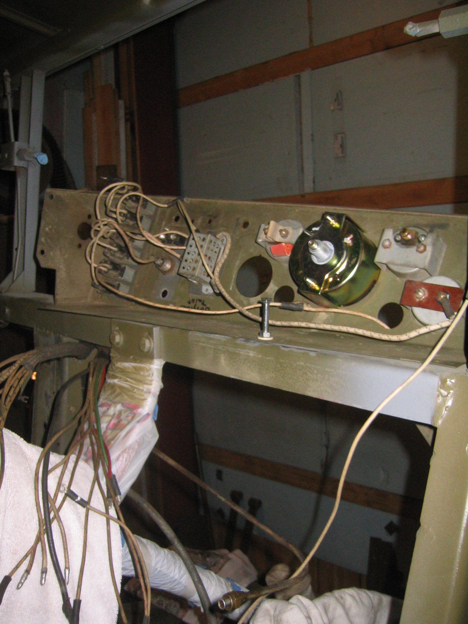
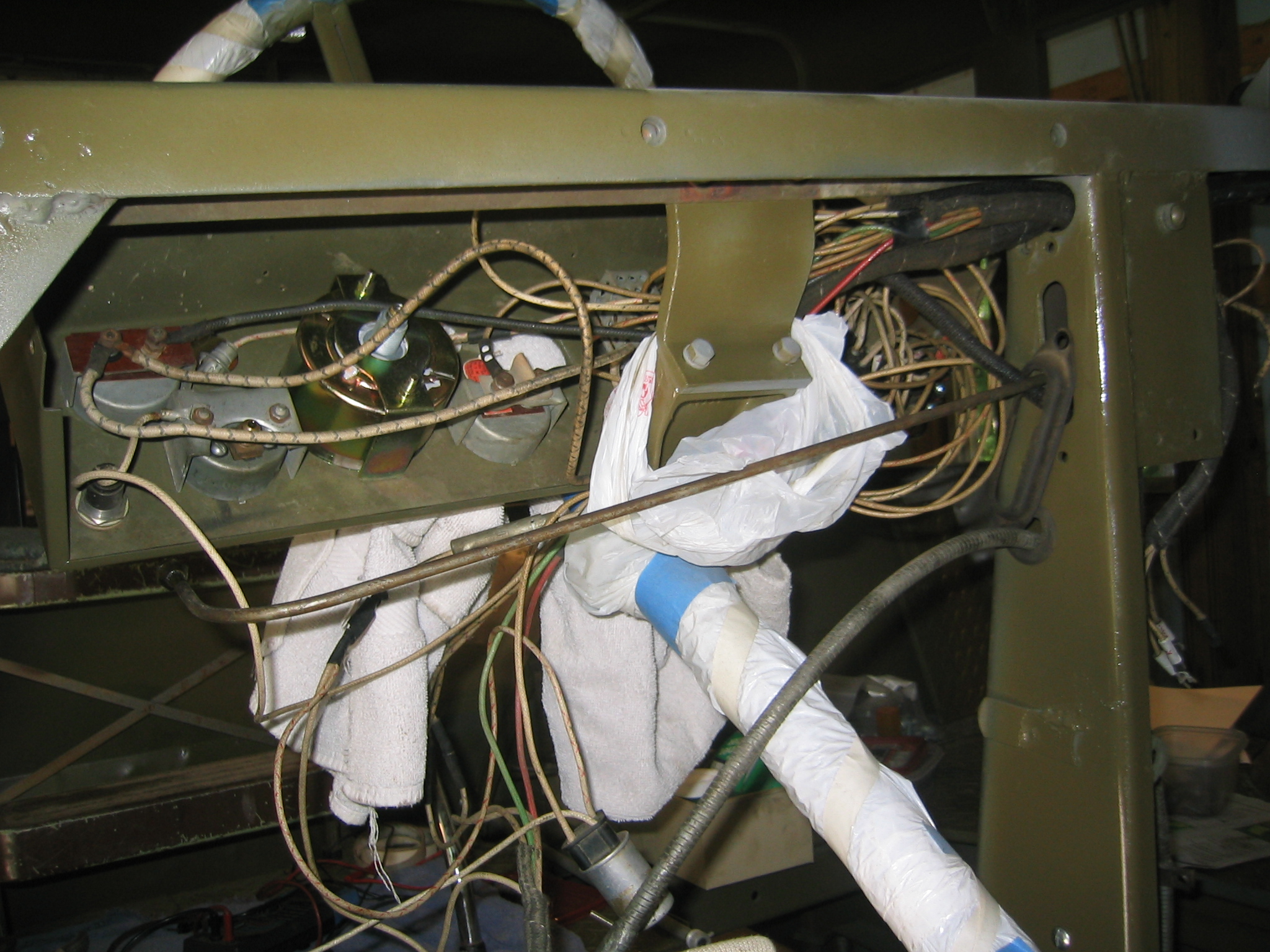
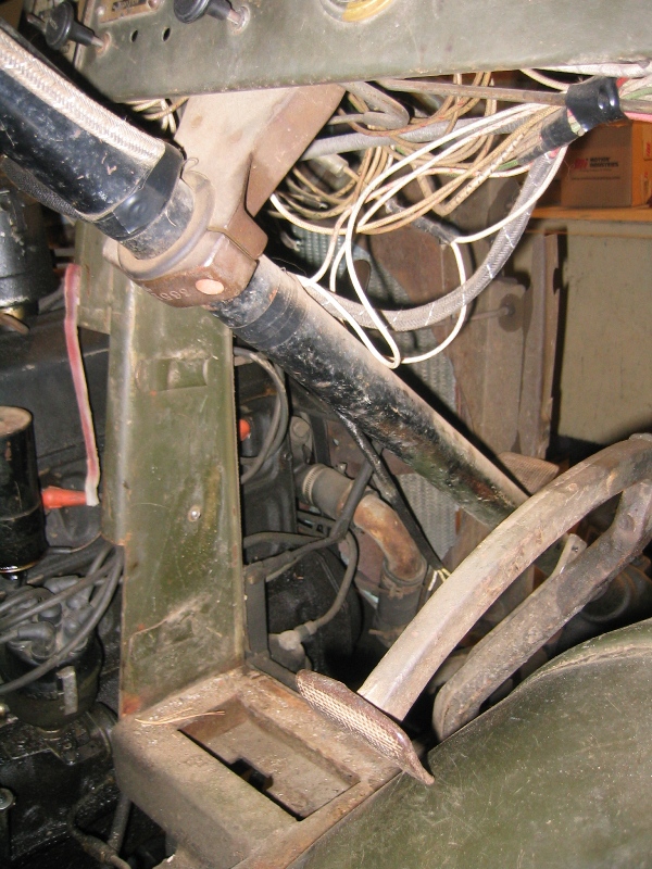
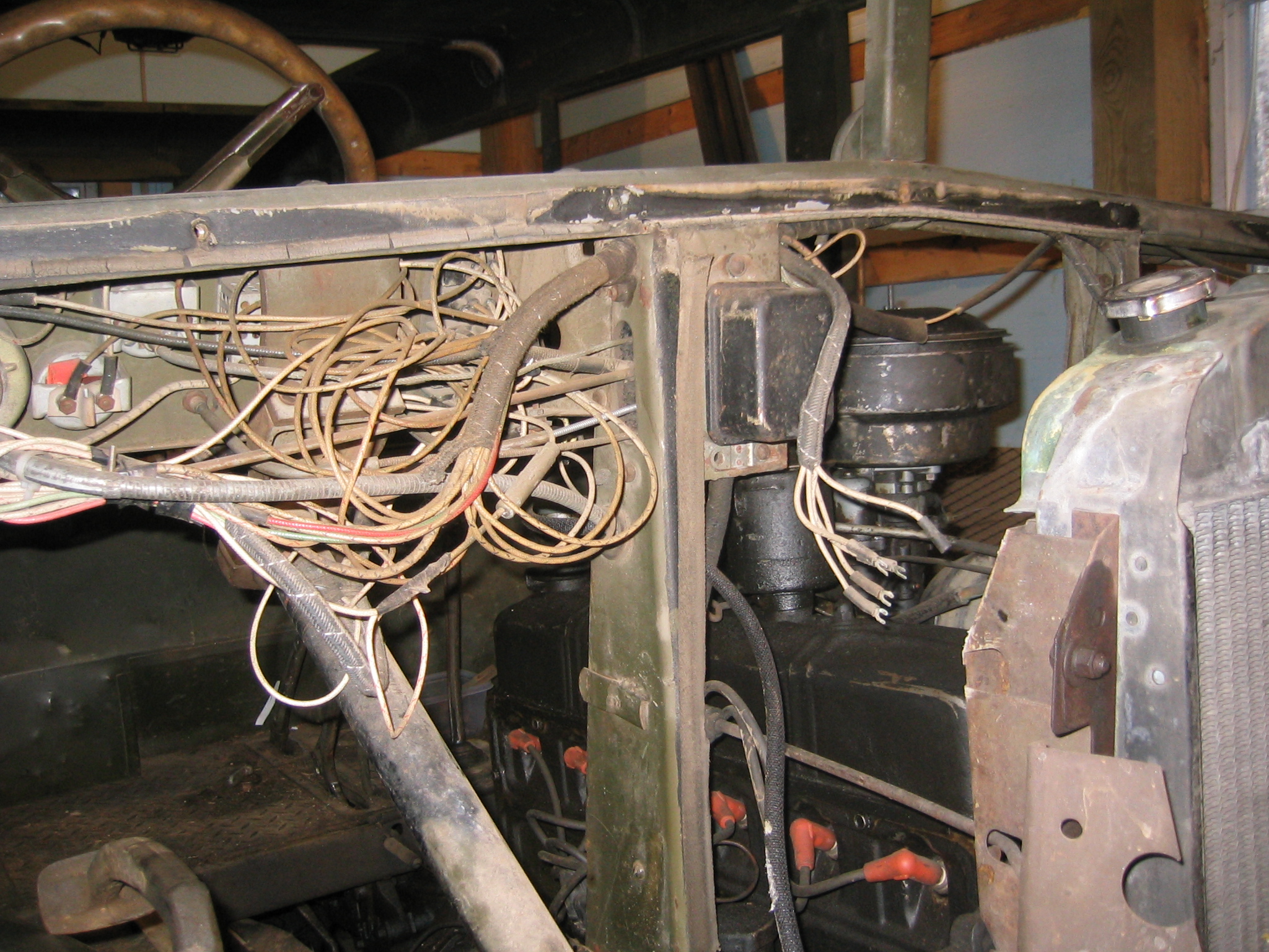
1. Take lots and lots of pictures showing how the wires are routed, where they are connected, where wire clips are placed, where each branch of the harness takes off in relation to the vehicle.

2. As you disconnect each wire tag it, I use masking tape and marker. Tag every wire it will save you a lot of time later.

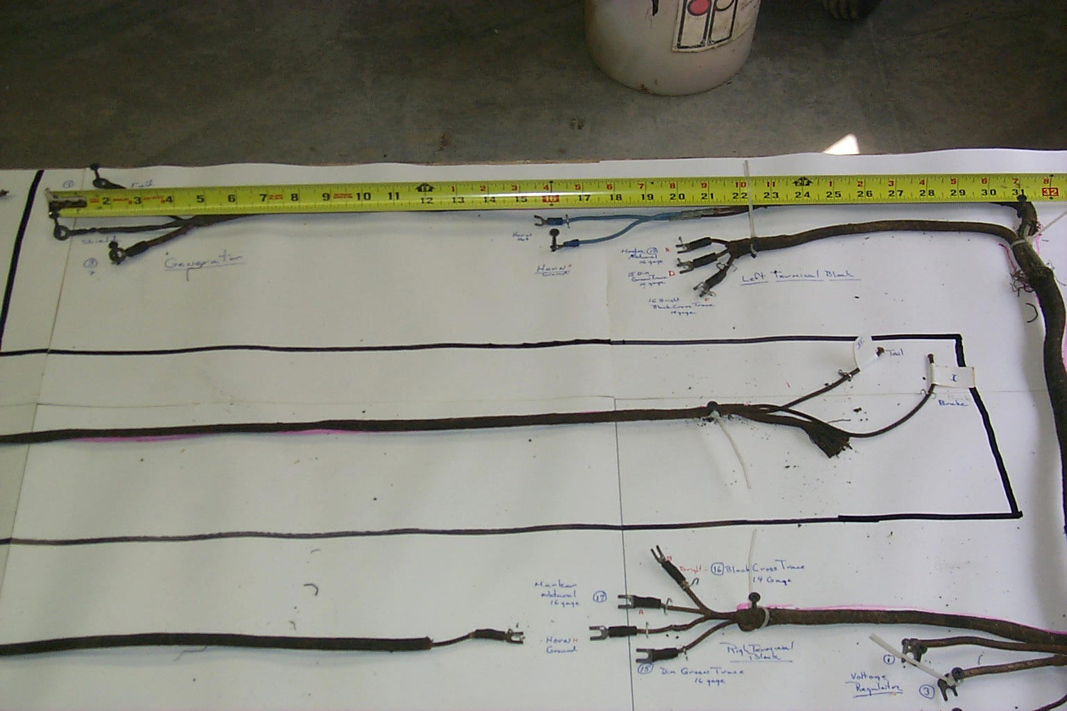
3. Get a plywood sheet 1/2 thick paint it white or cover it with white paper it makes it a lot easier to make notes.

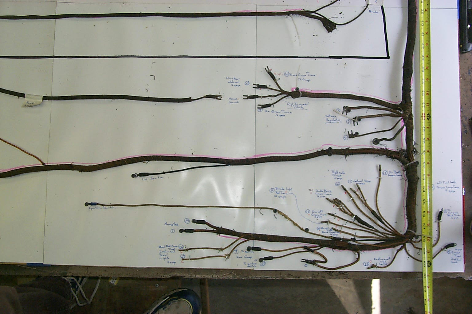
4. Lay out your harness on the so that nothing crosses over then using sheet rock screws and small cable ties tie the entire harness down being sure to put a screw at each location that a wire or branch of the harness takes off from the harness body.

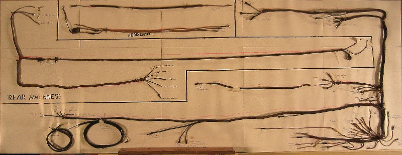
5. At the end of each branch of wires spread the individual wires out and staple them down to the board. Leave your old harness attached to the board during the rest of the process. ( I have all the old harnesses and their panels hanging on the wall of my shop. Each has been used several times now.)

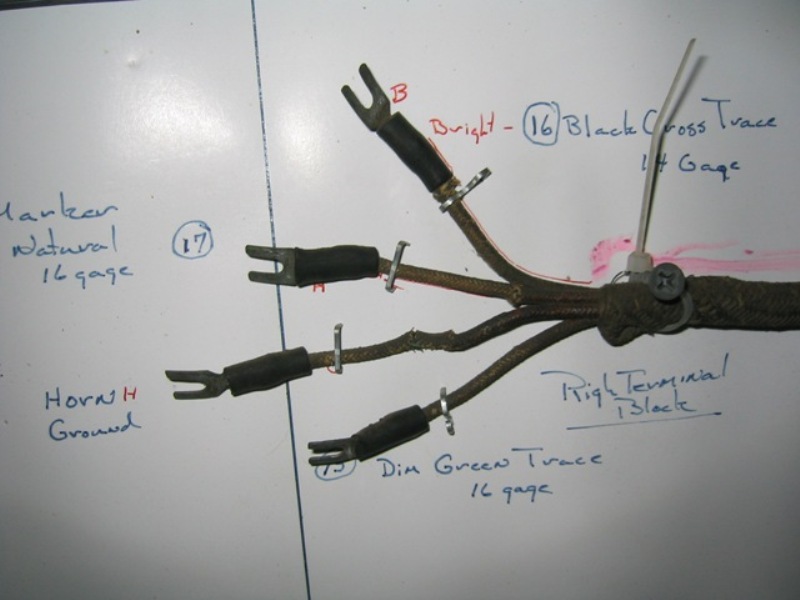
6. Now transfer your notes from the tags you made to the board. I generally add what color or color pattern the wire is as well as the size of the wire.

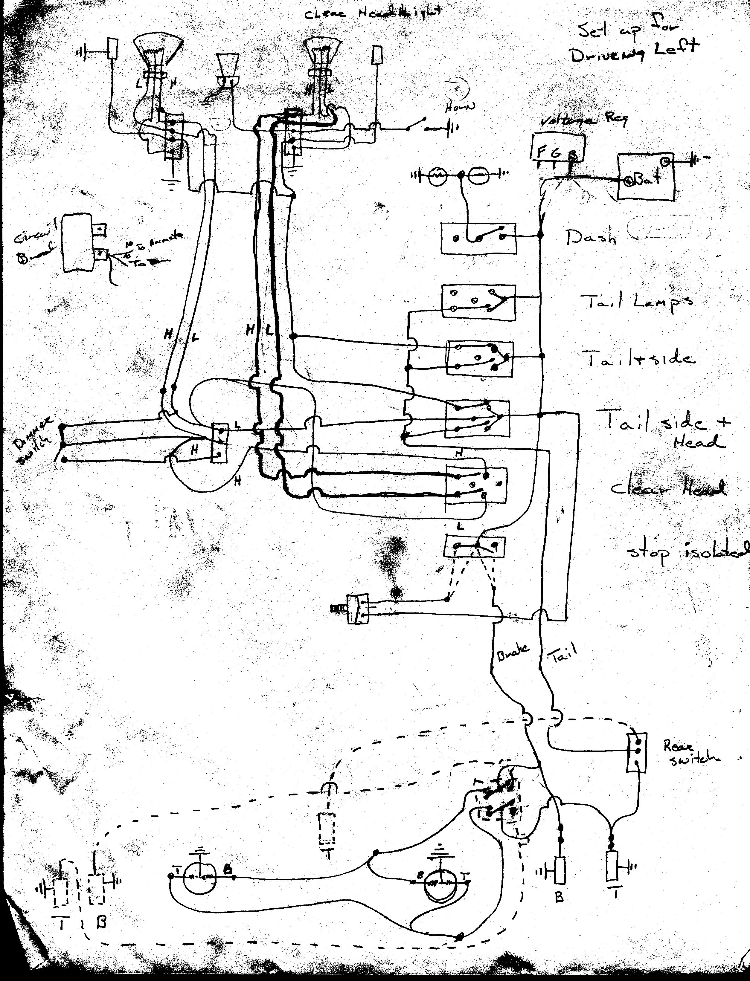
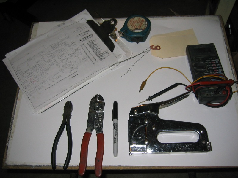
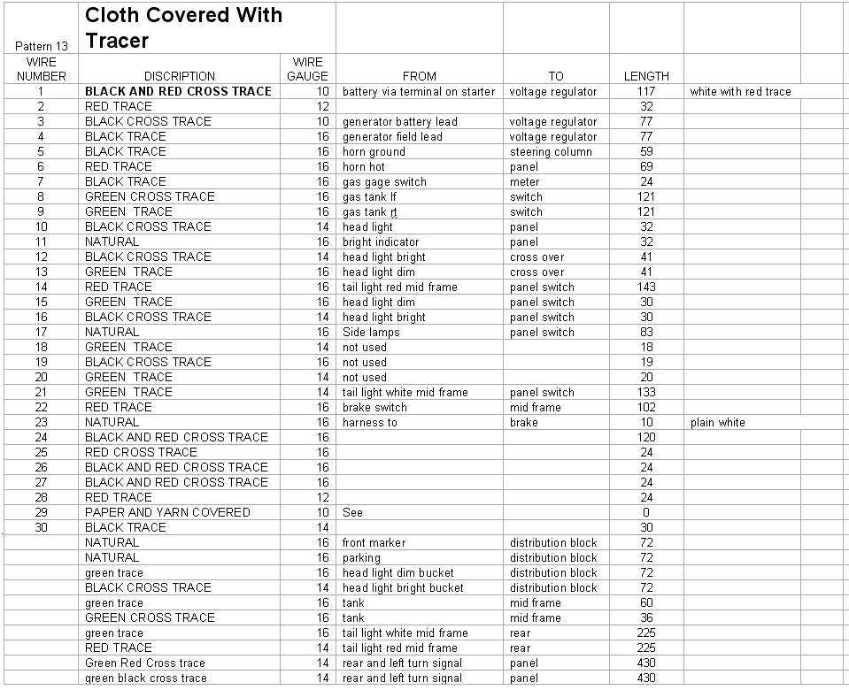
7. Then using the vehicle wiring diagram if you are lucky or the harness make up a list of each branch showing where it goes, wire color and size and gauge (there is an example on my web page) I do all this on a spread sheet.

8. Then measure all the wire lengths. Always add at least 6" to each measurement.

9. As many colors and wire patterns are used in several branches make a summary list of all the different wire lengths you will need.

10. Then find a source for the correct color wire, pattern and gauge. I always buy at least 10 feet extra of each required colors wire, pattern and gauge.

11. While your looking at wire sources find the terminals you will need.

12. Once you have all the wire. Lay your plywood panel down flat on a table and carefully start laying the new wires on I use little lengths of twist wire at each screw to hold the wires in place just loosely bind them to the screw, then as you add more wires you just untwist the hold wire. I use the thin old phone wire for my twist wires that thin copper wire works great.

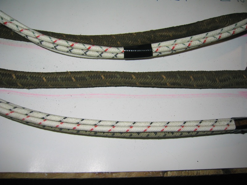
13. When you have all the wires are in place check it against your original harness. Smooth the wire in each leg of the harness and tape them at the point where the covering of the old harness ends. I use black electricians tape. Then go along the harness and about every foot and at each place that a leg or branch leaves the harness tape it again. I use a different color electricians tape this is to make putting the covering over the harness branches easier.

14. Now as to covering the branches their are various sources that will do the fabric or thread type looming used on early Lincolns such as mine. But I believe most of the more modern harnesses used a thin version of electrical tape which is wrapped in a spiral around the branches and body of the harness. Some of this type of tape is of a heat shrink variety.

15. If you are sending your harness out to be loomed don't put the terminal ends on until that is done.

16. Once the harness is wrapped or loomed put it back on your board and start adding the terminals, I always make my ends 2-3 inches longer than the original which makes connecting everything a little easier. This is also where the photos you took when removing the harness help full to decide how much extra you need.

17. Being old school I solder each terminal end to the wire instead of relying on crimp fittings.

18. Then using all those pictures you took put your new harness into place.

19. Be extremely careful to put all the wire clips used to hold the harness in originally also be very careful of where the harness is next to a source of heat or movement. I once left out the clips near the master cylinder and the speedometer cable they rubbed through and shorted out burning a two foot section of the main harness in the process.


The basic tools for the first step include a wiring diagram, which in the case of Chevy CMPs gives wire size, wire trace pattern, as various sections and terminal ends are laid out on the board the circuit #, wire size, and trace pattern. I use a curved staple staple gun meant for stapling telephone wire. The multimeter is used to confirm continuity of each individual circuits and also helps to trace wires which are not tagged during the removal process. The wire crimping took is used to identify the gage of each lead as it is marked down on the board.

Once the entire wiring harness is spread out on, attached to the board, and label then the process of of measuring and recording each individual length of each wire run is done. Below is the list for a 101" wheel base Chevy CMP, I say 101" wheel base instead of HUP because in the process of making up a number of harness over the years I have discovered that the Chevy Pat 13 front harness is the same on all length. What changes is the rear harness length. There are of course differences between Early Pat 13s with the Commercial Instrument Cluster and the Late with the Military Gauges. I have examples of both mounted on boards.

Please don't hold me to these figures with out confirming them on your own truck. The LENGTHS shown are in INCHS. As wire is sold in feet I always round it up to feet and quite often round up to next 10 foot length.

The original steel wire with cloth covering is not available but what is available is copper wire with modern vinyl insulation which is in turn covered with the correct colored woven covering with the correct color tracing as shown above. Going from steel to copper wire while keeping the gauge the same will give a slightly better current flow.

There are a number of very good sources for these materials that also carry many if not all of the correct wire terminals. Check out Rhode Island Wiring Service Inc. http://riwire.com/ and Vintage Wiring of Maine http://www.vintagewiringofmaine.com/Home.html I have bought material from both and they are excellent, and I can recommend both. They both offer looming services which puts the correct over loom on the harness and branches.

Once you have all the different wire in the original, correct colors, and wire gage, you start laying out the new wires on wire board on top of the old harness tying it down to the screws that hold the original harness in place. Cut the wires 2 inches longer (at each end) than the original. The reason for this is that they made the harness tight to save wire but that also makes routing extremely tight. The little extra lengths just makes insulation a lot easier. As you can see from the photos below, which are `45 HUP, that the wiring behind the dash is extensive and tightly routed. In these pictures some of the friction tape that is used to tie the individual wires up out of the way has been removed so the wires are hanging down lower under the dash than normal.

When I do a harness I add extra wires to the harness for turn signals which are run in the same legs of the harness as the marker lights.

(Future addition to full discription of making harness but for now I'm going to skip to details of the HUP harness)

Note also that the Nose of HUP has been removed to gain access. While some wiring work can be done from under the dash, if any significant work such as installing a harness is to be done removing the nose will save many times the time necessary to remove and install the nose. One other point ALL WAYS DISCONNECT THE BATTERY WHEN WORKING UNDER THE DASH there a lot of exposed terminals that are easy to short out.

The reassembly process after the 2011-2012 Overhaul - Reusing the earlier made harness was relatively straight forward as I was not having add or replace connectors or parts.

The backside of the instrument panel was one of those areas that I decided not to repaint leaving it the original color and paint as something for some future restorer to find.

When I first copied the harness years ago I need something more than the standard wiring diagram below

The problem in particular was understanding the logic of the instrument panel switch, I've always meant to redo this drawing on the CAD to make a clean copy, but each time I have tried the original drawing is still more useful.

In the picture above note the three position terminal strip this is the connection point for the high/low beam of the headlight on my HUP this switch is mounted on the floor to be operated by foot. On some of the earlier Pattern 13s the same switch was mounted in the side of instrument panel note the one and two small holes.

Unlike a conventional car or truck where the power would come from the light switch to high/low switch then to the head lights on the HUP the power goes to the high/low switch then to the two switches for the head lights