Rip Van Winkle Lincoln
Body Work Begins
Page 2
Restoration of 1949 Lincoln Cosmopolitan Town Sedan
A year has gone by but work has been continuing. As with many
restoration project this one has not been going as expected. The condition
of mechanical components turns out to much better than expected, while the
rocker panels which looked OK in places turned out to be undercoat over rust.
As the interior was stripped out the true condition of the
floor and rocker panels became more clear. As did the amount of structure
inside the rocker panel and all of it was rust held to together by memory
and not much else. I'm afraid that this may well be the Achilles Heal of the
Cosmopolitans.
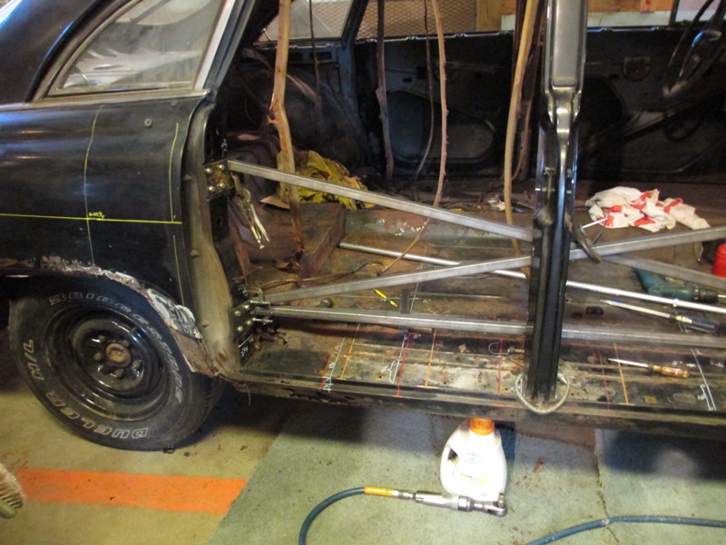
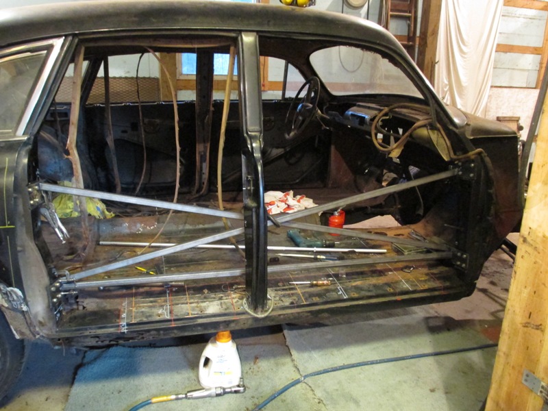
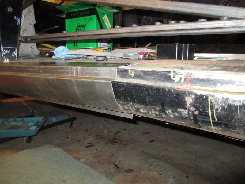
With all four doors of the Town Sedan opening with smooth action
and closing with a solid thunk keeping everything aligned became a priority.
Along with taking very careful measurements of the position of everything.
Figuring out how to brace and hold the body straight and true as the structure
of the rocker panel is removed and replaced was very important.
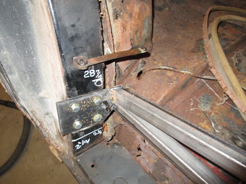
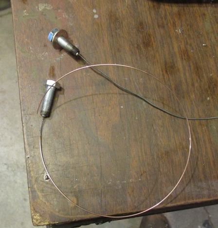
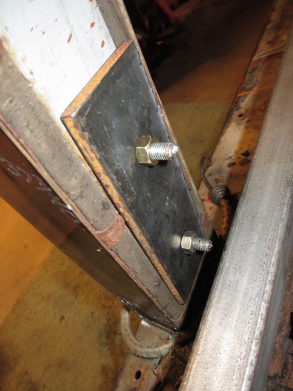
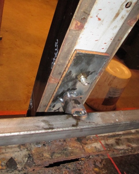
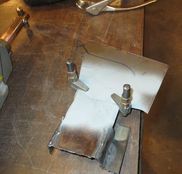
To locate center door post, it was necessary to tie the door
post into the X bracing, part of the problem was how to bolt a mounting plate
to the door post without adding more holes that might cause problems later
particularly when the door post is basically a box structure. Fortunately
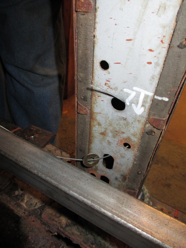
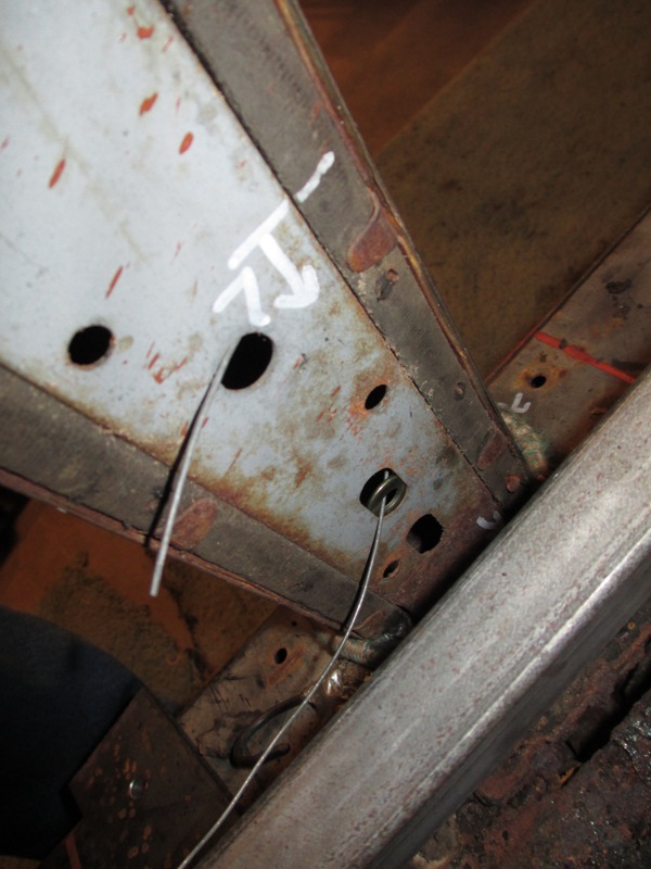
it had several bolt holes, but how to get a bolt in from the blind side, there
is an old trick of welding a fish wire to the thread end of the bolt the wire
can then be inserted from another location and out the hole to be used.
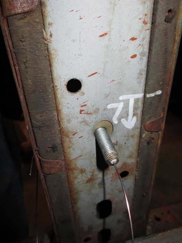
Of course when the brace is removed I'll have to remember to
fish out the bolt and washer, or it will add an unwanted rattle. In the past
this has been done with a magnet on a string.
(Note several months later it when the brace was removed the
bolts did drop down inside the post and now need to be fished out. My revised
plan for the other side will be to drill a small hole through the end of the
bolt so that a string may be inserted when it is time to remove.)
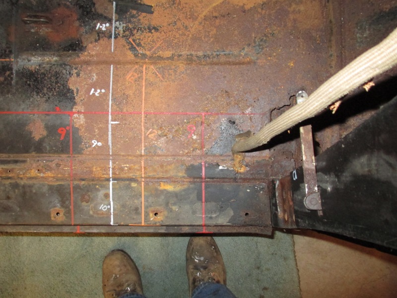
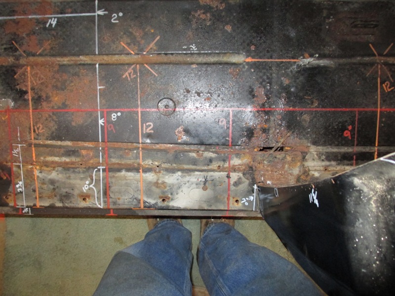
The other important step was to establish witness points to
align the new parts to, this was done by painting lines on the floor of the
car with measurements to the location for the actual rocker panels.
Once this was done then I started making sketches and measurements
of what the structure of the rocker panels and the backing structure.
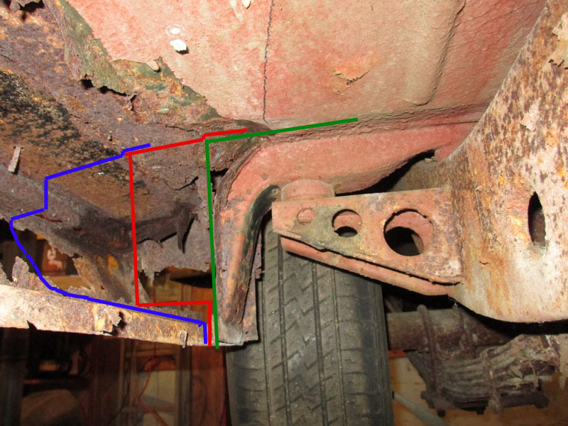
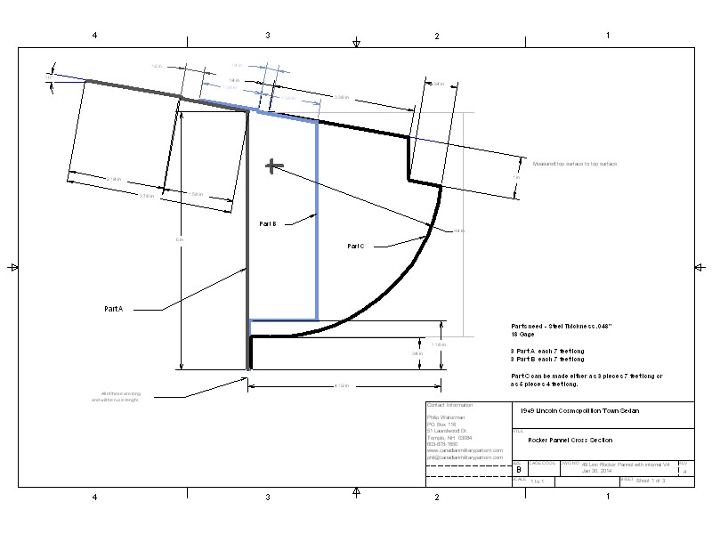
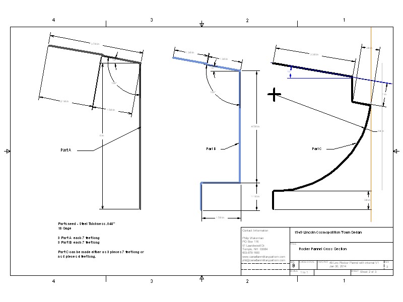
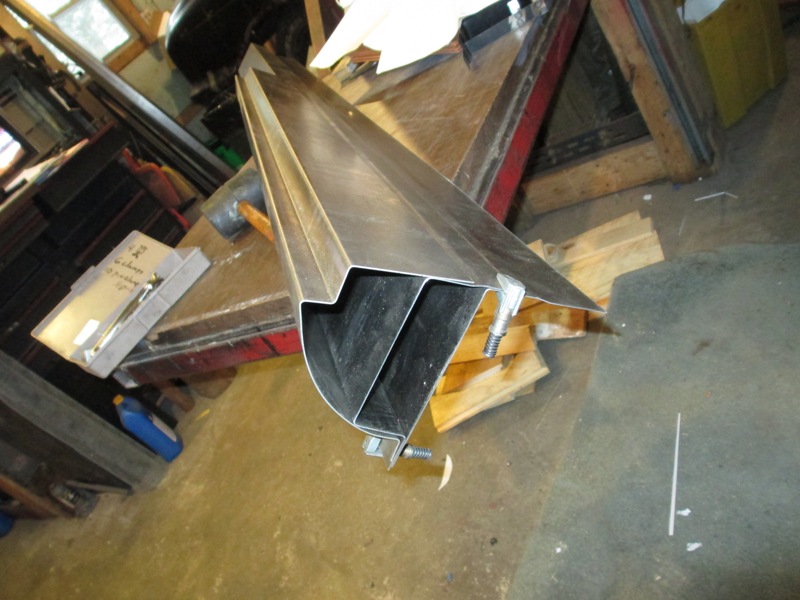
It took making many samples to determine what the cross section
of the rocker panel structure was along the whole length. As these parts were
all stampings they were not straight bent units as would come out of a metal
brake. Took longer than expected to make CAD drawings.
I tried making the rocker assemblies on my own metal BRAKE
but found that consistently bending 18 gage sheet metal accurately was just
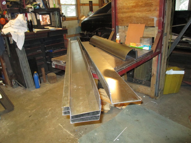
not in the cards. In the end I took the CAD drawings to a sheet metal fabrication
shop I asked for 3 sets of 7 foot length which would have give me one extra
of each, just in case I screw up. For $350 they made me up three lengths of
8 foot long of the components. They were going to charge me for the entire
sheet of sheet metal so they just them 8 foot long, giving 24 liner feet of
each section. The car will actually need only 13 liner feet of each so if
I don't make any mistakes there will be enough for a second Lincoln.
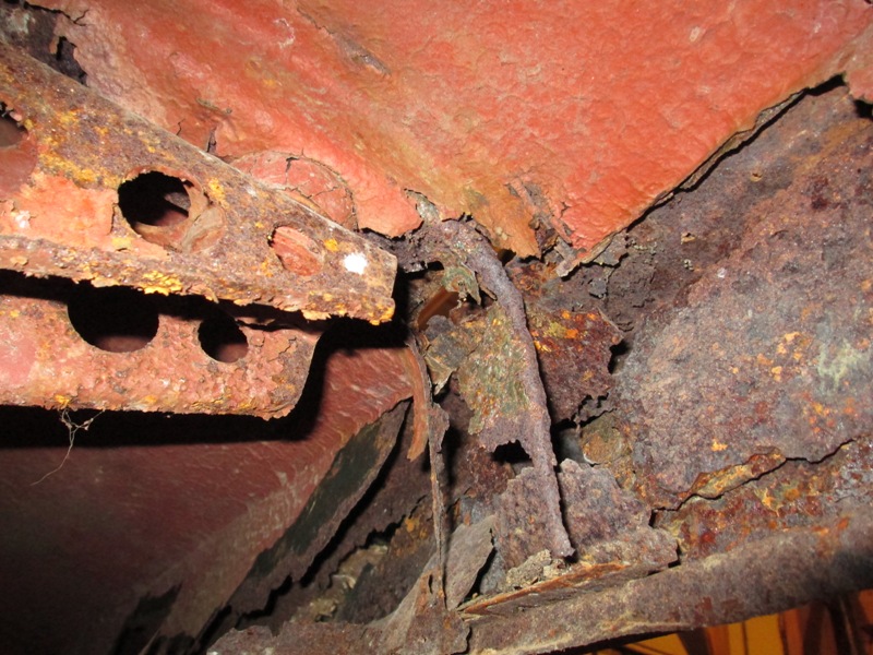
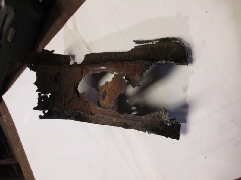
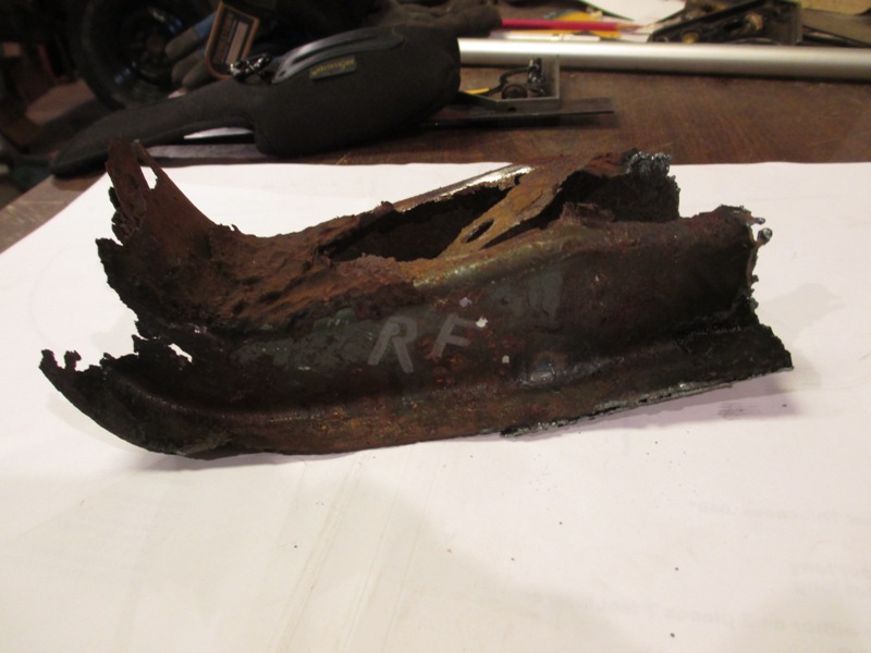
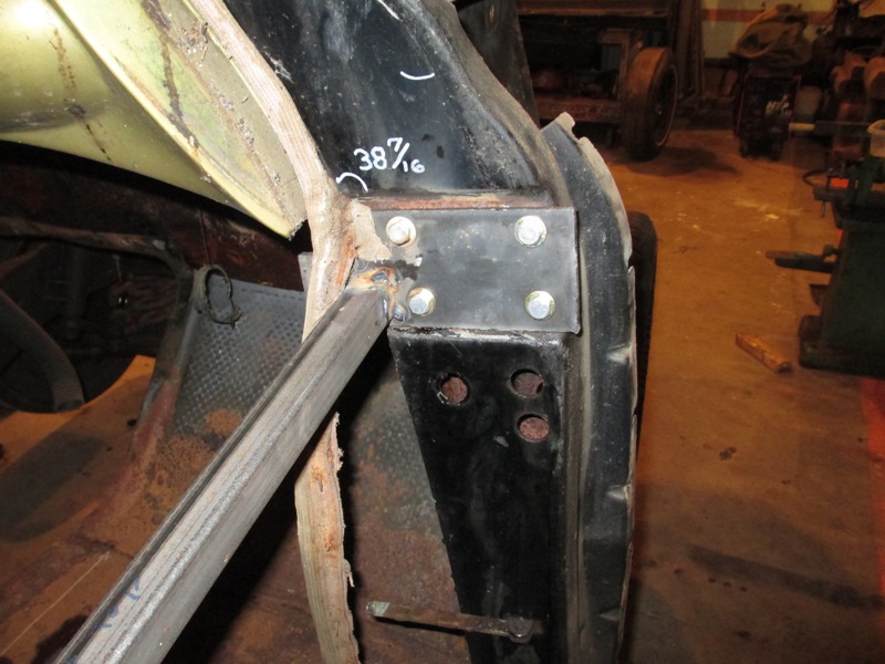
Above two pictures show what one of the body mount look like
when it was remove. The other one that was remove totally disintegrated.
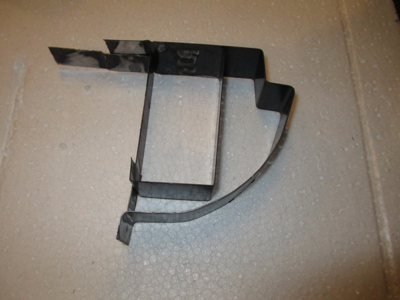
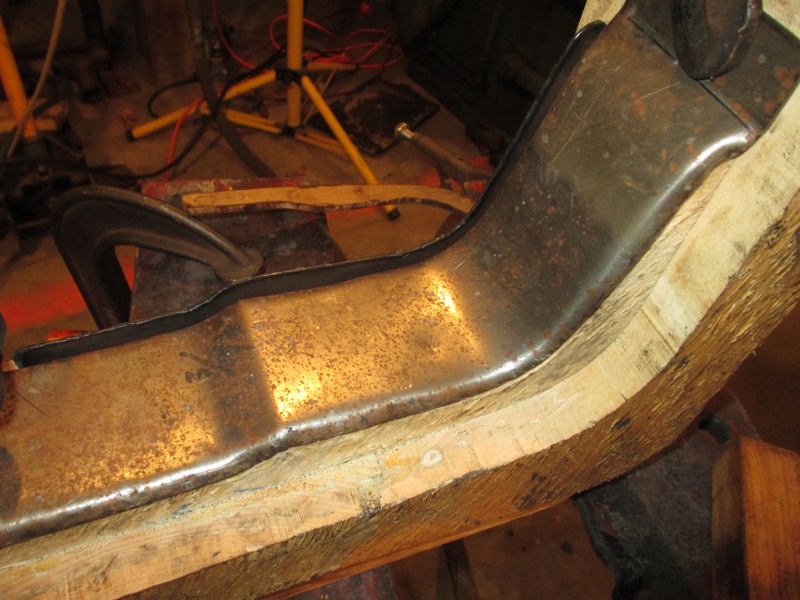
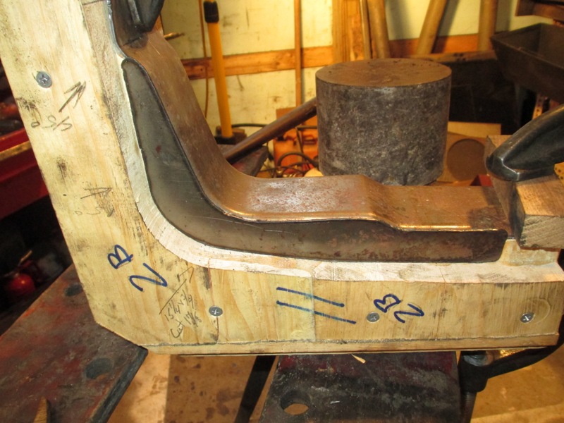
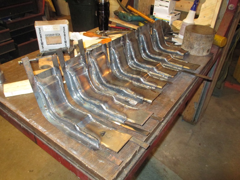
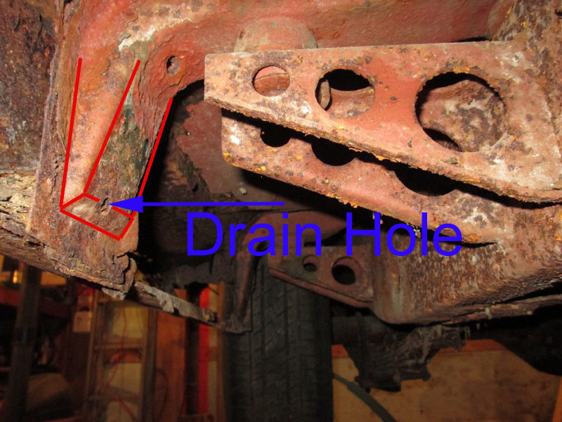
As can be seen from the photo above ends of the cross body
HAT Channels that also located the back side of the rocker assembly need to
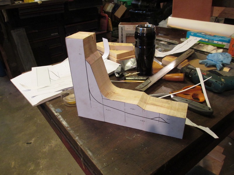
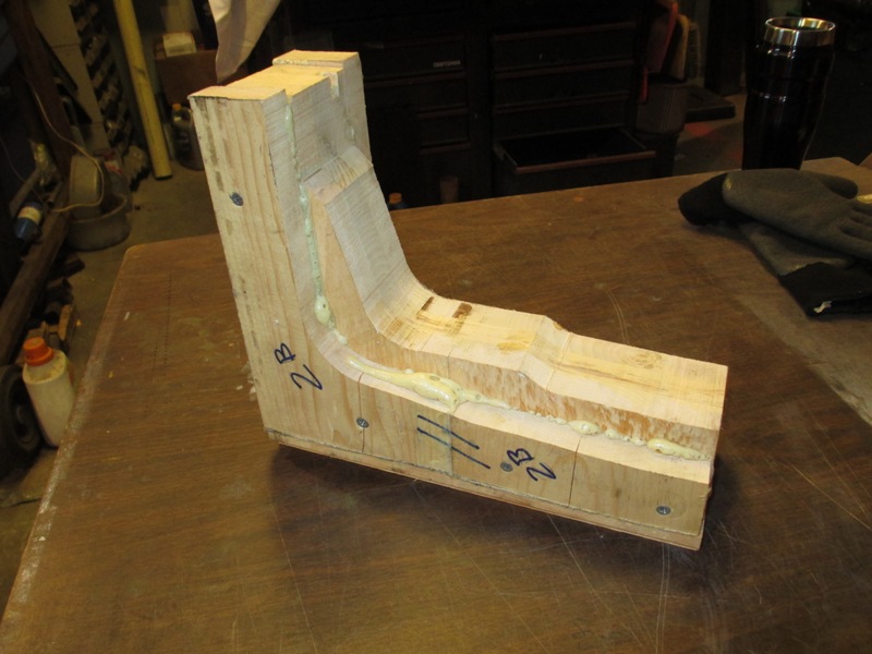
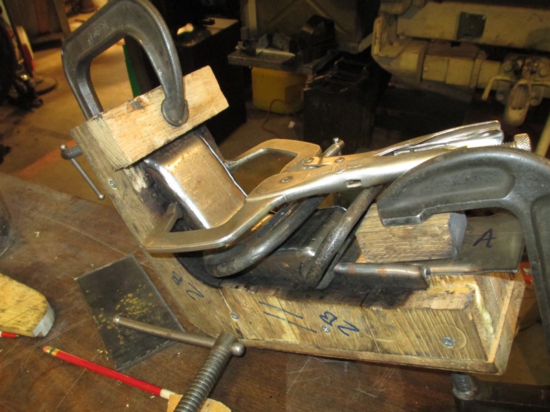
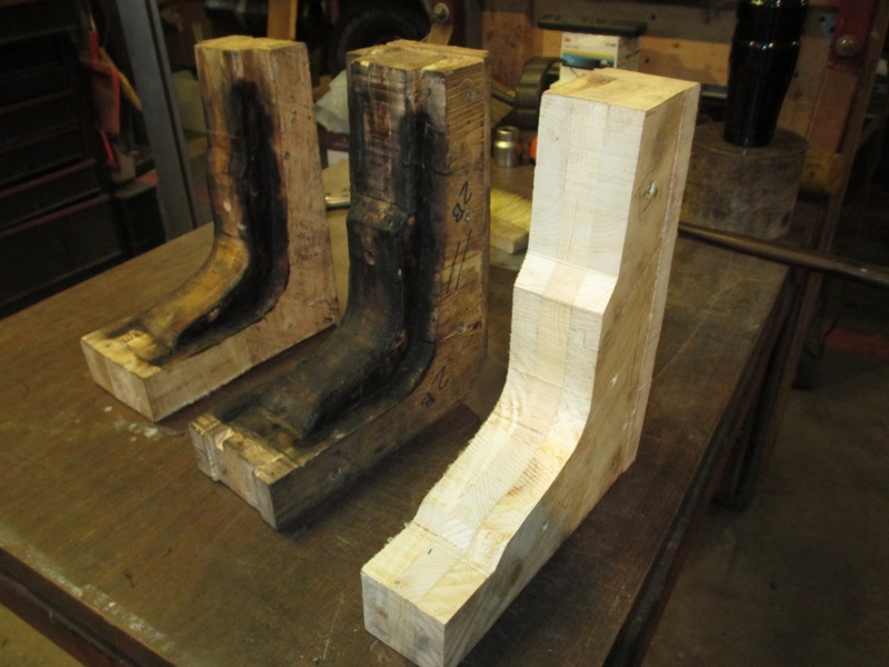
be fabricated as well. From the drawings templates were made to make metal
forming BUCKS this was done by gluing layers of wood together to make up the
needed width and then cutting them out on the band saw To make the cut out
process a little easier I printed the drawings out full size on Avery Shipping
Label stock, using the blank 8 1/2 x 11 full sheet label stock. In this way
the self adhesive sheet can just be stuck on the roughed out BUCK that had
been glued up. (Photo below left) Then the two side parts of the BUCK are
glued in place to form the sides of the HAT Channel.
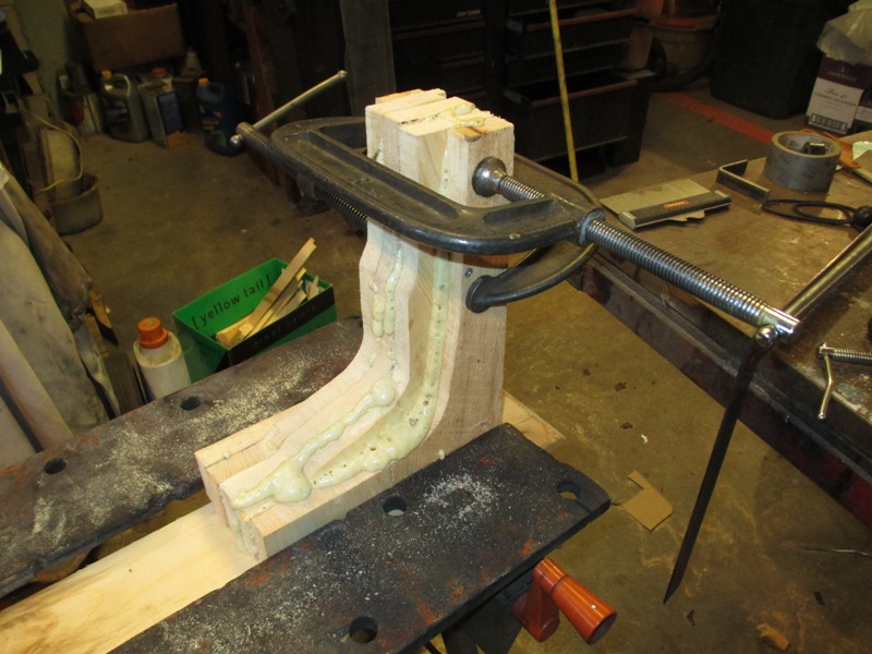
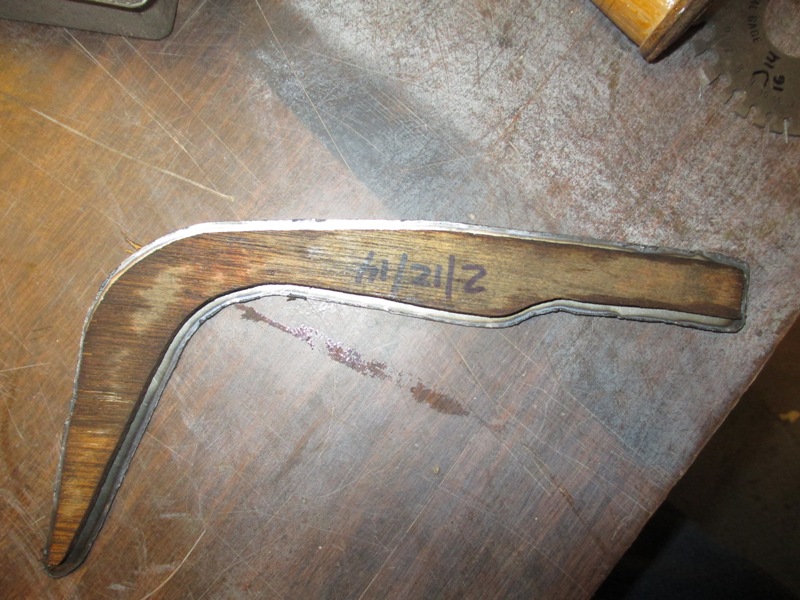
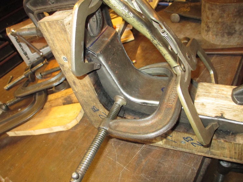
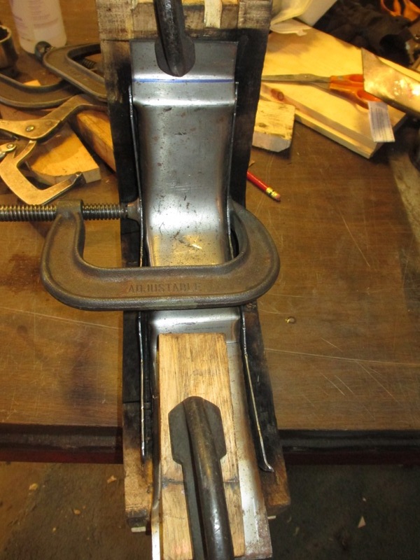
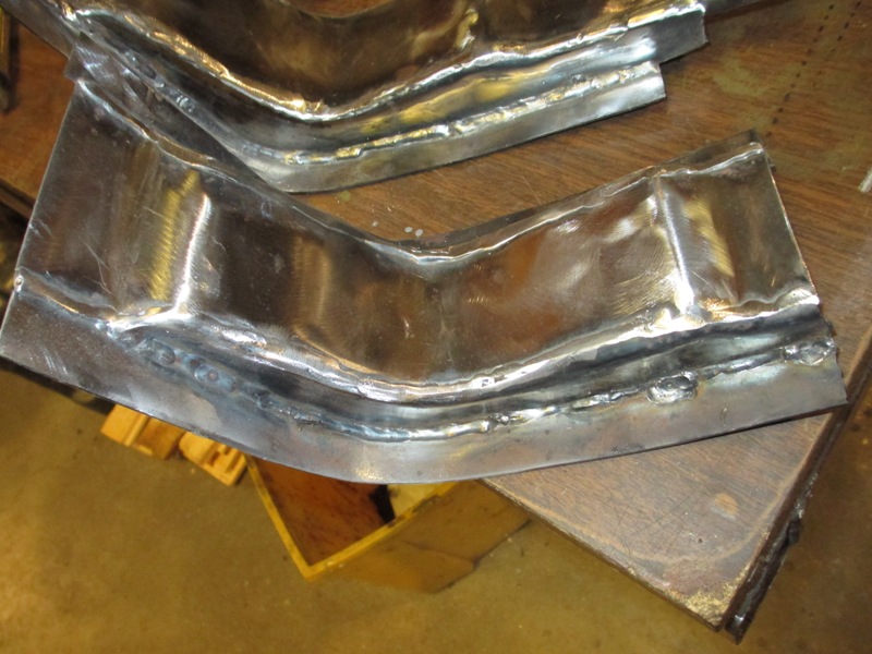
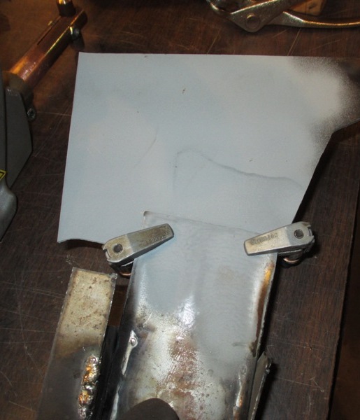
Once the glue as cured the BUCKS can be used to form the
sheet metal in the picture above right is the face of the HAT channel that
has been cut slightly wider than required and the edges beaten over to start
the curve edge of the HAT. Bending this material over also stiffens the face.
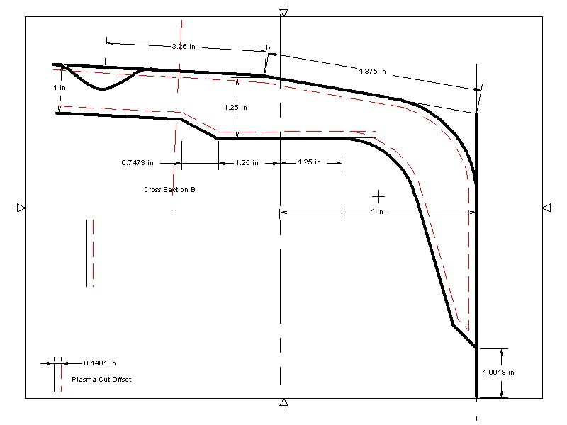
Then the sides of the channel are cut out with plasma cutter. Now if you are
lucky enough to have a digitally controlled plasma cutter you feed in the
drawing and it cuts them out. Not having a digitally controlled unit the alternative
is to make a template the cut out the sides. In the drawing below right note
the red dashed line this is how far from the edge my template has to be for
my plasma torch. Once again the drawing is printed out on label stock which
is then stuck to the thin plywood and the template is cut out using the red
line to cut by.
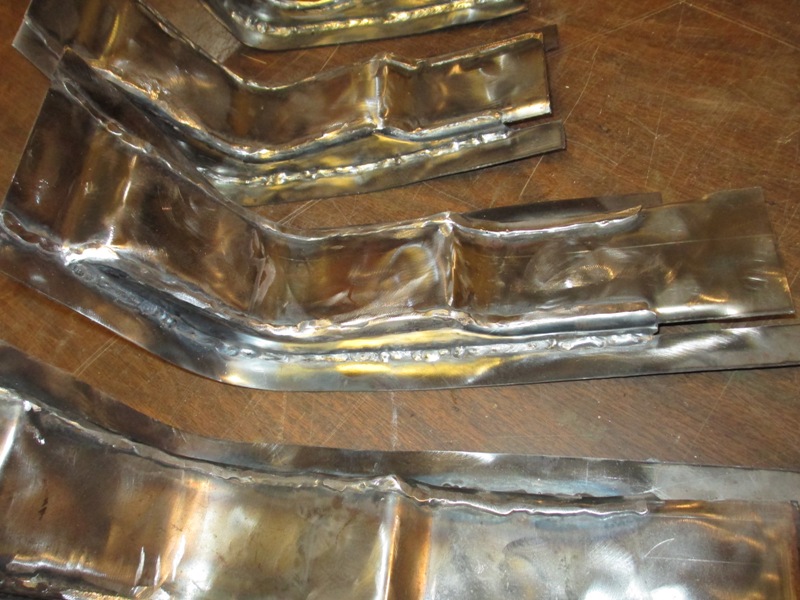
The Hat Channels got gradually better as I did more but with
a little smoothing once they are painted and then undercoated the difference
should be hardly noticeable.
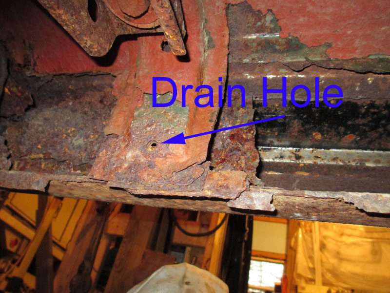
The original Hat Channels had a drain hole that was not
at the lowest point which is something I will correct. As the Hat Channel
is spot welded flat against the back wall of the rocker panel assembly this
provided a location for rust to start.
As it is hard to paint the inside of things like Rocker Panels and Hat Channels
the plan is to paint the insides with a primer sealer in areas that will not
be welded. In the areas that will be welded I plan to use Zinc Weld Thru Primer.
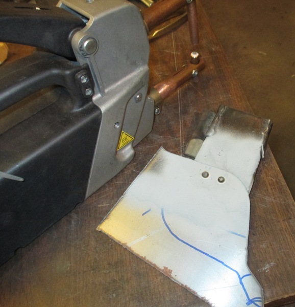
To better understand how this products works, did some test welds on 18 gauge
steel with both Mig Welder and with Pinch Spot Welder.
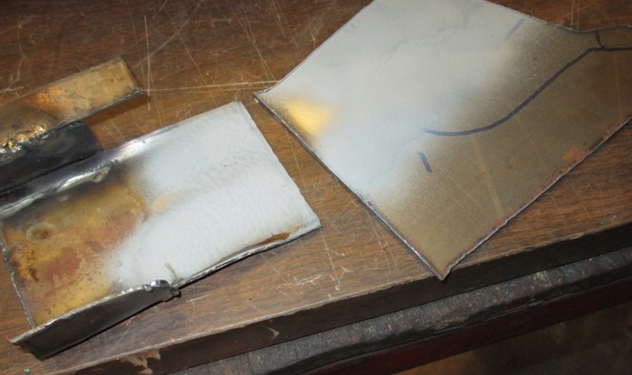
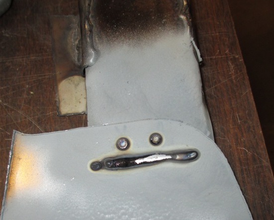
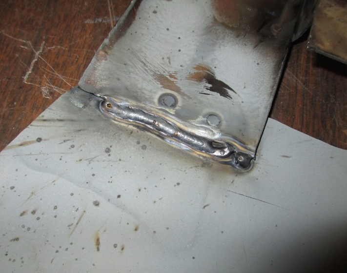
In doing the experiment discovered that the paint will wipe
off when the steel was still hot from welding. The Zinc Weld Thru Primer did
work well as far as electrical conductivity which the pinch spot welder is
very sensitive to, even thin normal paint will provide enough insulation that
the welder will not work. Just to test the little sample I have put it outside
the shop were the water drips of the eves of the roof.
The plan is to provide good low point drainage for any new
panels installed and to provide plug holes for spraying in oil.
Rocker Panel work continues on Rip Van Winkle Lincoln Page
3.
Jump to
Return to
Rip Van Winkle
Lincoln Page 1 History
of the Vehicle and Beginnings of the Restoration