Sheet Metal Work Begins in EarnestFebruary 22, 2005 on going |
||
|
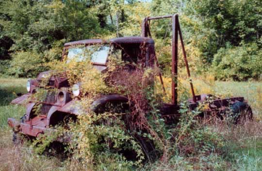
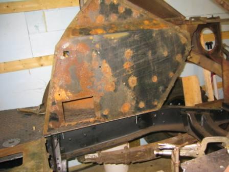
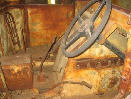
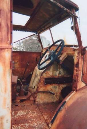
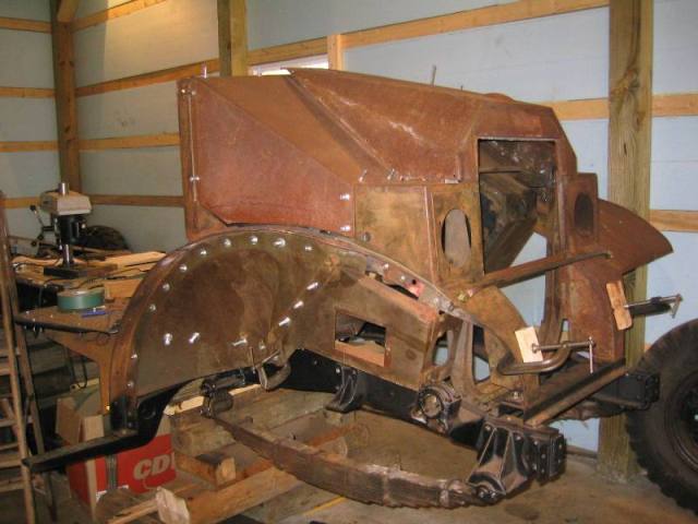
As the saying goes RAN WHEN PARKED What they don't mention is that it was parked in 1960. The this page will be dedicated to sheet metal work on the 1941 Patter 12 C60L. This truck sat out in the weeds for some 50 years and as you can see from the pictures there was hardly and paint left. In fact it was hard to tell what color the truck had originally been painted. No paint meant rust, which left the decision as to approach to restoration given the basically simple design of the CMP with mostly flat body panels. The choice was to replace any heavily rusted panel or to repair only the rusted areas. Replicating and replacing rusted or damage part would result in a more perfect restoration but repair will result in a more original truck. For now I've decided to go this latter route. |
 |
|
| One thing I learned in restoring old cars
is that the temptation is to start with the most interesting and visible
parts of the vehicle. The problem with this for those of us who don't
do body work for a living is that means that our learning or relearning
curve is taking place on the most obvious and visible parts of the vehicle.
So I always have to discipline myself to start with the most hidden body
work, things like the bottom of the battery box or the inside of a foot
well and then progress to the more interesting parts. Hopefully that my
skills will improve as I move along.
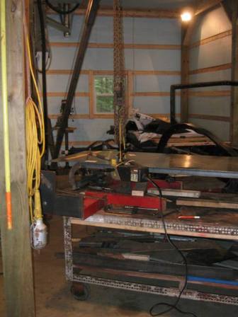
In most cases I'm make full size paper templates of each panel before I start repairs, in doing this should the repaired panel really come out bad, there will still be the information to fabricate a new part. Also if some one is looking to replace a missing panel on a truck I'll have information on file to help. Basic body shop tools that will be used include: 140 amp Mig Welder, 35 amp Plasma Cutter, normal sheet metal snips, 48" home made bending brake, drill press, 10 ton porta power kit, sheet metal hammers and dollies etc. |
 |
|
|
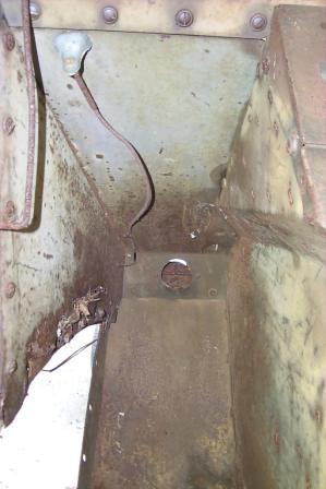
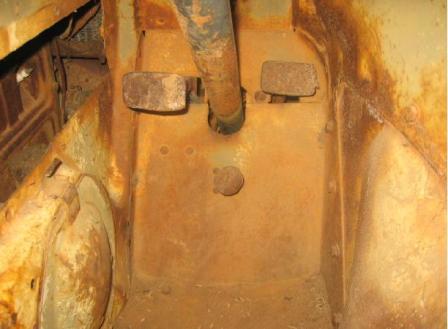
Taking lots of pictures before and during disassembly will greatly aid in the process of assembly and refitting parts |
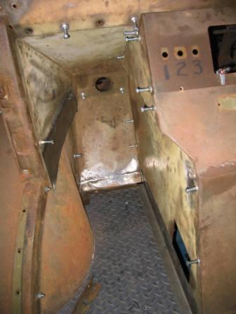
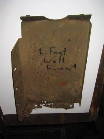
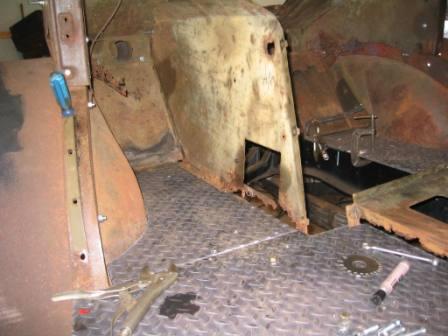
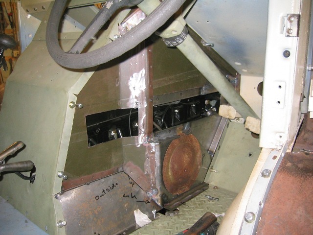
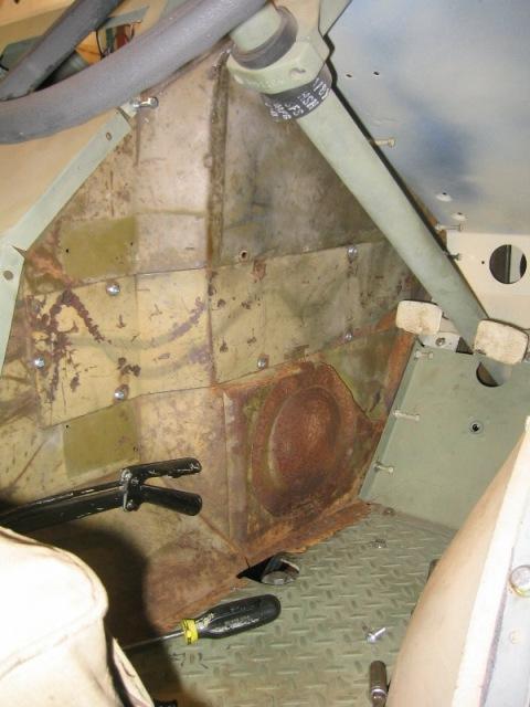
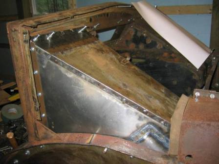
Here the foot well is being fitted after all the rusted areas have been cut out and replaced. During |
|
 |
 |
|
|
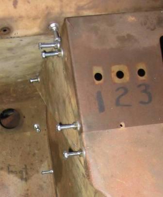
When fitting panels I find that it is much quicker to use a bolt with a nut started on the threads, rather than trying to screw each bolt all the way home. By grasping the bolt head it is easier to start the bolt or remove it, and a quick twist of the nut will tighten the bolt. |
|
|
|
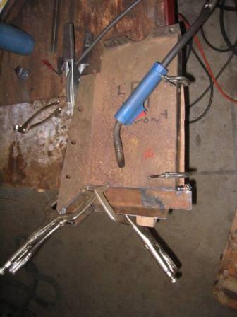
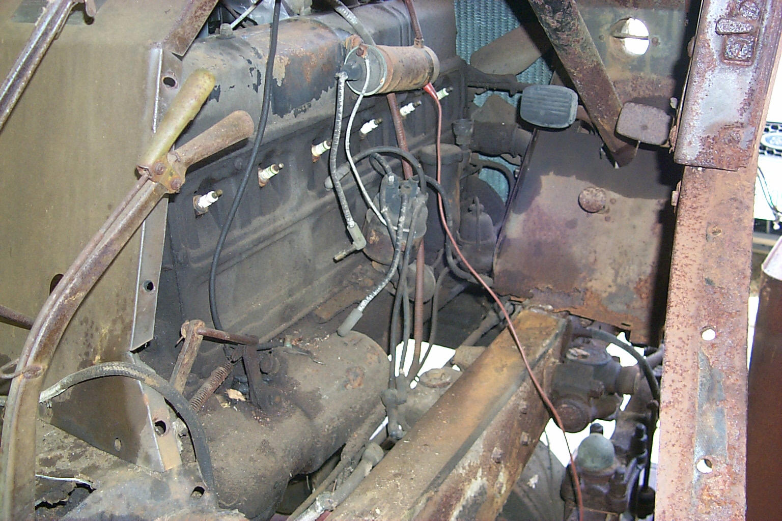
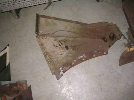
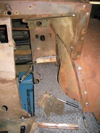
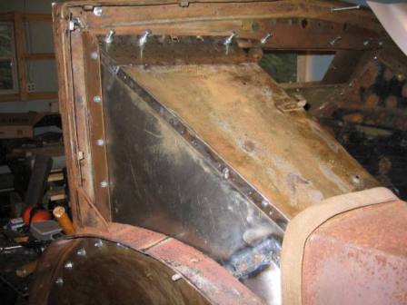
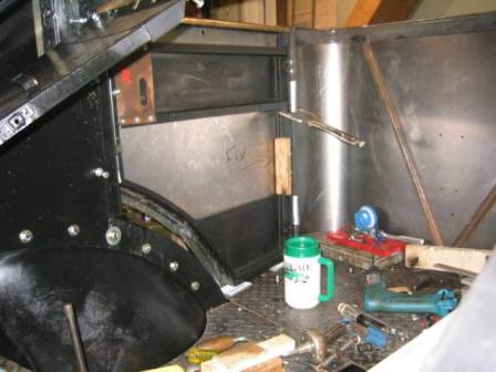
Left side of the engine compartment being traced for a template for future reference. Picture to right shows same panel with rust areas having been cut out and replaced. |
 |
|
 |
 |
|
|
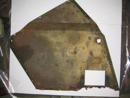
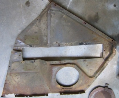
The right hand engine cover was missing so the first step is to collect photos of the what the part looks like. My apologies for not being able to credit many MapleLeaf Up friends who have provided them over the years. |
 |
|
 |
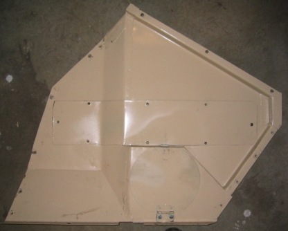
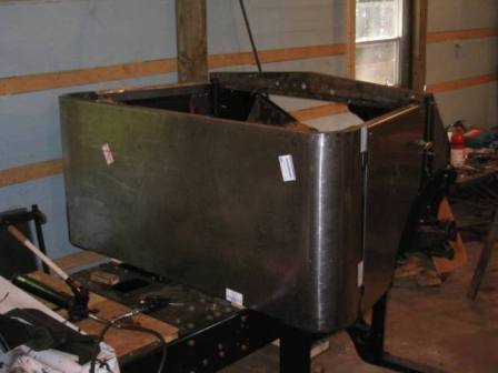
Bob Carriere- was kind enough to loan me two side panels to use as patterns below for making up a new side panel. The result below left is slightly different but is a close Proximally. |
|
 |
 |
|
|
|
|
|
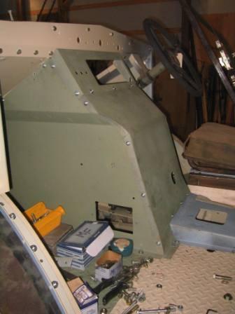
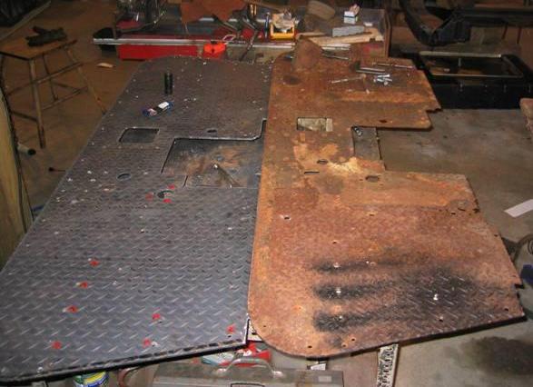
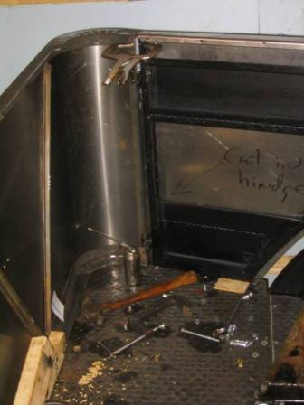
| The reproduction has will have to cut to allow removal without having to half disassemble the cab. | The original panel has been cut into two pieces, this is clearly to allow the panel to be removed without having to remove battery, battery box, rear engine cover panel, gear shift lever and transmission floor cover. | |
 |
 |
|
|
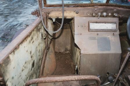
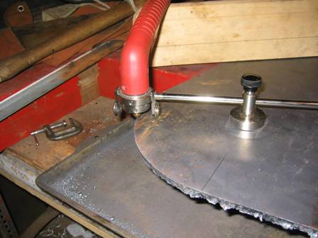
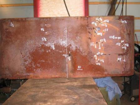
Work on the cab began with fabrication of new floor plates this was done by carefully copying the remains of the rusted original floor. In places the 1/4 diamond plate floor was completely rusted away. As the old saying goes measure twice cut once. All of the cuts and bolt hold locations were marked out prior to cutting anything. Cutting out the plate was done with the small plasma cutter. Which given taking it slow did and excellent job. Once the plate was cut to size then all of the numerous hole locations were checked on the new floor with size of hole noted next to the each location. Small bench type drill press was used to do the drilling (see Tools) by removing the base plate of the drill press and turning the drill table it became an easy matter to clamp the drill table to the plate and drill the numerous holes having marked all the holes and sizes first considerable time was save in drill all of one size before changing to the next size. |
 |
|
|
|
||
|
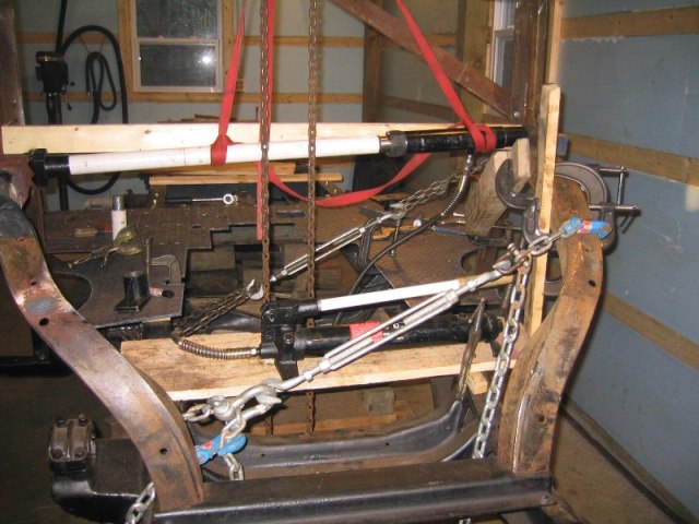
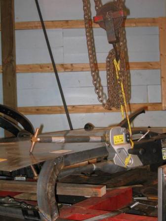
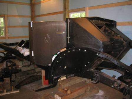
Right After the new floor plates been fabricated, they were bolted in place and the process of straightening the cab frame began. What had not been original evident was that the truck at some point appears to have been rolled and the cab frame on the drivers side was bent out of position an inch to two inches. On the right you can see a 10 ton aorta power hydraulic ram being used to straighten the cab frame. The chains and turn buckles are there to control where the bending actually takes place. The heavy angle iron construction of the cab resisted bending and showed a great deal of spring back. In the end it became necessary to jack the sections into alignment then use a torch to heat the cab frame at the points that I wanted the bending to take place. Below During and after straightening the cab frame the sheet metal was refitted several times to check the alignment.
|
||
 |
||
 |
 |
|
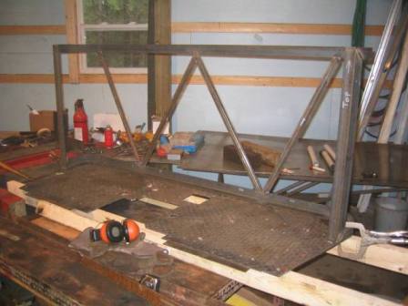 |
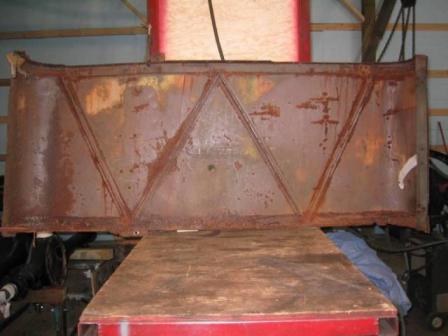
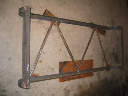
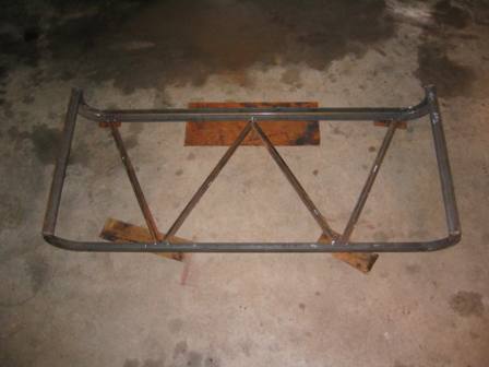
Above Left Then work on the cab back began, the back was in such poor condition that it had to be basically fabricated from scratch as with floor detailed measurements were taken and these measurements were transferred to the new skin. Above of the cab back only the W brace pieces where reusable. Left the new cab back frame Below & Below Left the skin is spot welded to the angle iron back frame suspending the pinch welder makes it much easier to align the welds. To keep the uniform weld appearance of the original panel all of the weld points were marked prior to starting. |
|
 |
 |
|
 |
 |
|
 |
 |
|
 |
 |
|
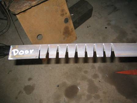
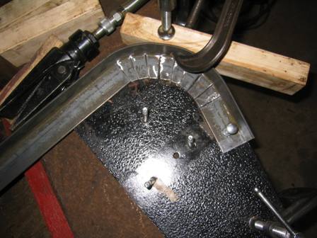
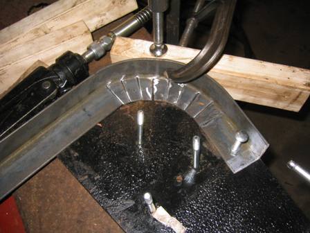
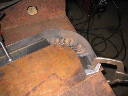
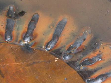
| The entire back of the Cab had to be refabricated. Lacking the tools to cold bend the 11/2 x 11/2 angle iron, cutting the top and bottom edges with V notches allowed bending with a porta power unit. Once the bends were completed at the desired radius then each notch was mig welded. Important in the strength of weld is that each notch needs to have an open space of 1/6-1/8 of inch this allows for good weld penetration. | ||
 |
 |
|
 |
 |
|
 |
 |
|
 |
 |
|