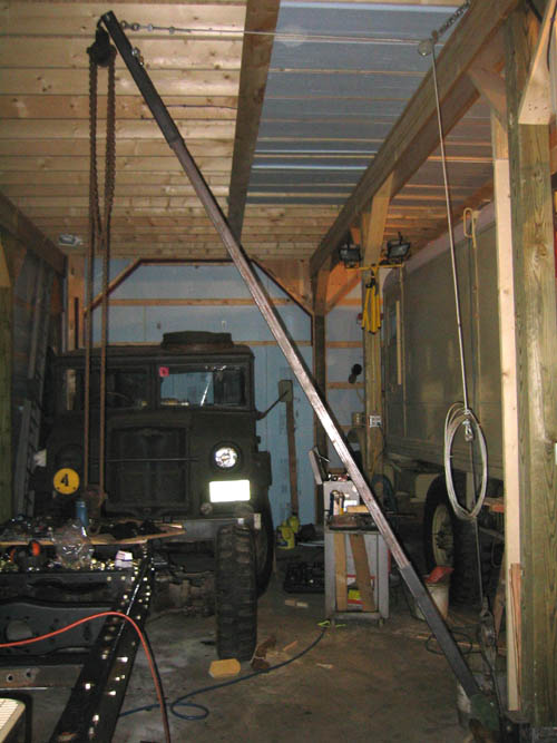
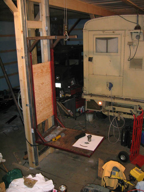
| Thus equipping the shop with a boom jib hoist that can pickup assemblies from anywhere in the work bay makes disassembly and reassembly much easier. The boom is made of 2x2" box tubing with a swivel at the base and chain hoist at the tip. Boom is adjusted with the come along which allows great adjust ability in out as well as 180 swing. | Picture below shows the platform lift for moving parts and tools from the storage loft to the work area. Not having to carry parts or tools up and down stairs means that the loft area is extremely useful. The electric hoist will lift loads up to a thousand pounds, so engines transfer cases etc. go up and down with no problem. A side benefit is that it also makes an excellent adjustable height work bench. |
 |
 |
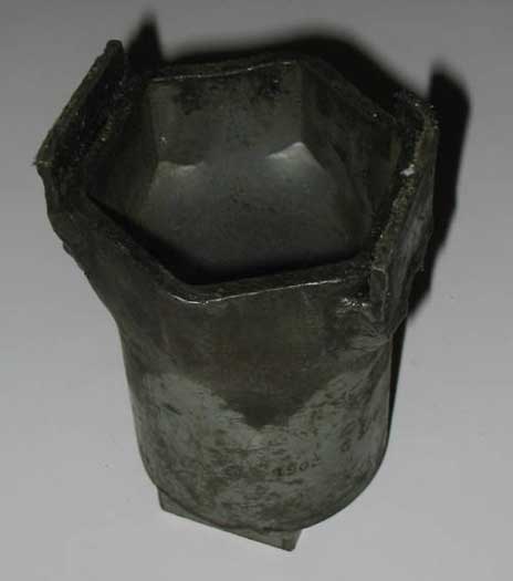
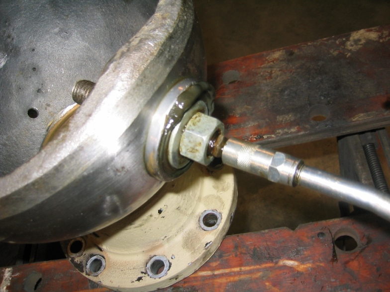
| Wheel axle nut socked for the HUP has one
of the first tools that I had to adapt the front requires a inch and the
rear requires a inch socket . Then large socket wrenches were not easy
to find. As it turns out the smaller socket out side dimensions was same
as the so by welding a layer of 1/8th in steal around the outside it also
fitted both front and rear. While the adaptation looks rather crude it
has work well for more than twenty years.
Though I've never had a problem on the road that required removing a brake drum this tool lives in the HUPs tool box along with a socket wrench. Think about trying to disassemble then reassemble front or rear hub with out it. |
 |
|
The next special tool was to re-lubricate the Front Wheel Pivot Pin Bearing the manual says that these bearings are permanently lubricated and should not be cleaned put replaced. Now if the grease has hardened and no replacements are available what do you do? You clean the bearings and make a tool to force new grease into the bearings. This simple little tool is made of a length of threaded stock that has been center drilled and tapped to take a grease fitting and side drilled to allow the grease to come out between the nuts. Then with washers of different sizes different small bearing can be re-lubricated.
|
|
| Another simple lubricating tool is for adding fresh grease to the front end universal drive balls. These according to the manual are suppost to be disassemble every 5000 miles cleaned and relocated with a couple of pounds of grease. Every thousand miles you are supposed to remove the plug in the axle balls and add grease. If you just put a grease fitting in and pump away the new crease is added at the outside of a 6" ball of grease. Instead take a length of 3/8ths copper tubing crimp a grease fitting in one end. Then with the wheel jack up insert the tub until you hit the universal joint in the middle then give it 5-10 squirts with the grease gun. Then withdraw the tool rotate the wheel 180 and reinsert the grease tube and shot away again. This gets the newgrease directly into the center of the ball. | 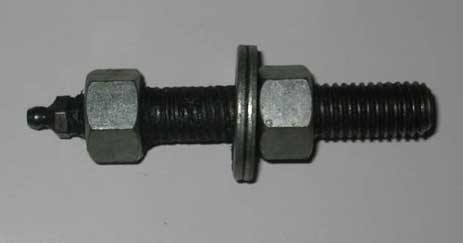 |
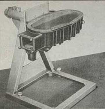
| Pictured below is a standard inexpensive engine stand from the local auto parts store which with a few minor adaptation serves both as engine stand and transfer case repair stand. | |
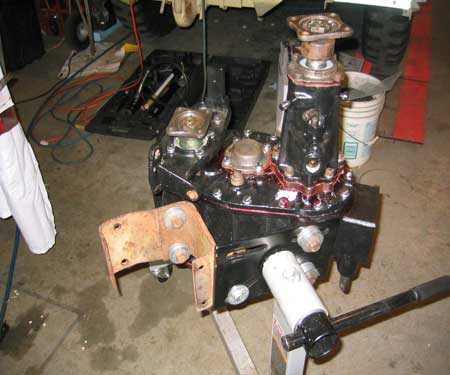
| The transfer case on a CMP has got to be one of the most award assemblies to work on difficult to remove and position to work on. The manual instructs you to use Repair Stand J-1716 to hold the transfer case while working on it. The unit picture is a nice four legged stand that allows the transfer case to be rotated or flipped over to adjusted the bearing preload. | |
 |
|
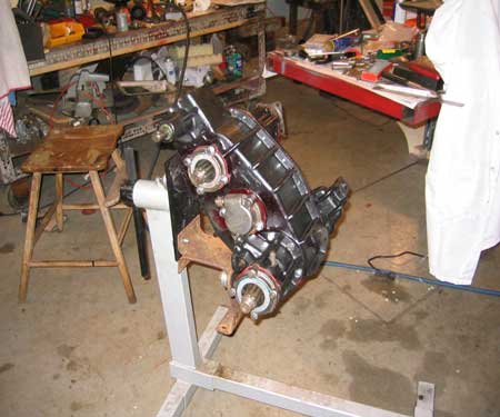 |
Now when you go to work on the engine it advise that you use Universal Engine Stand X-6000 in this case the same inexpensive engine stand shown holding 216 engine for work.
|
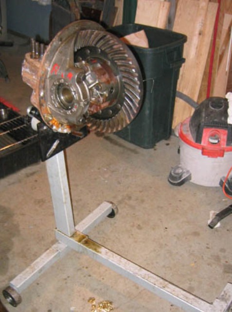 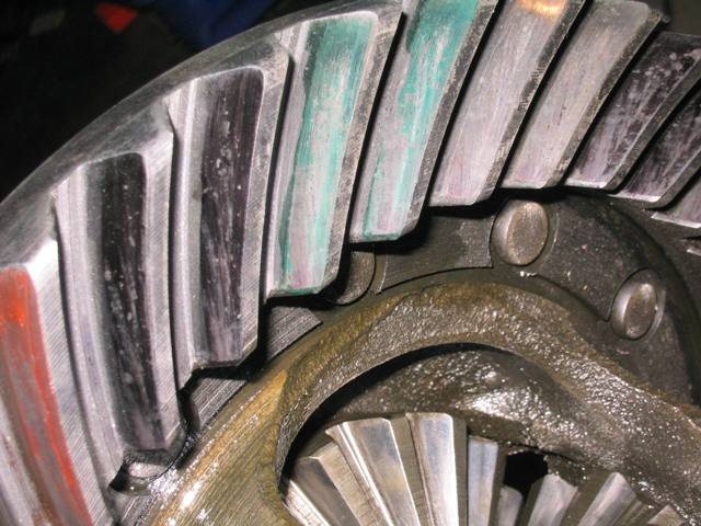 |
Setting up differentials is also easier with unit mounted up on the stand it allows the gears to be more easily turned while the play backlash is being adjusted out. The manual calls for check the gear set up is to coat the gear teeth with a mixture of redlead and motor oil. Well a modern replacement is magic marker. Color a couple of teeth then turn the pinon while loading the ring gear a couple of spins in both direction and the marker is worn off . The wear pattern is then match with the manual . I use different colors as adjustments are made. |
 |
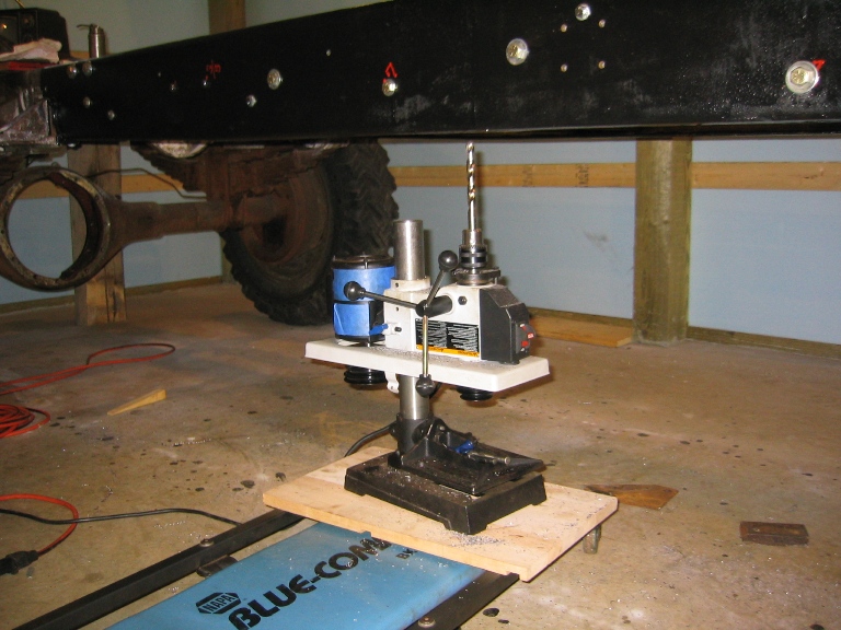
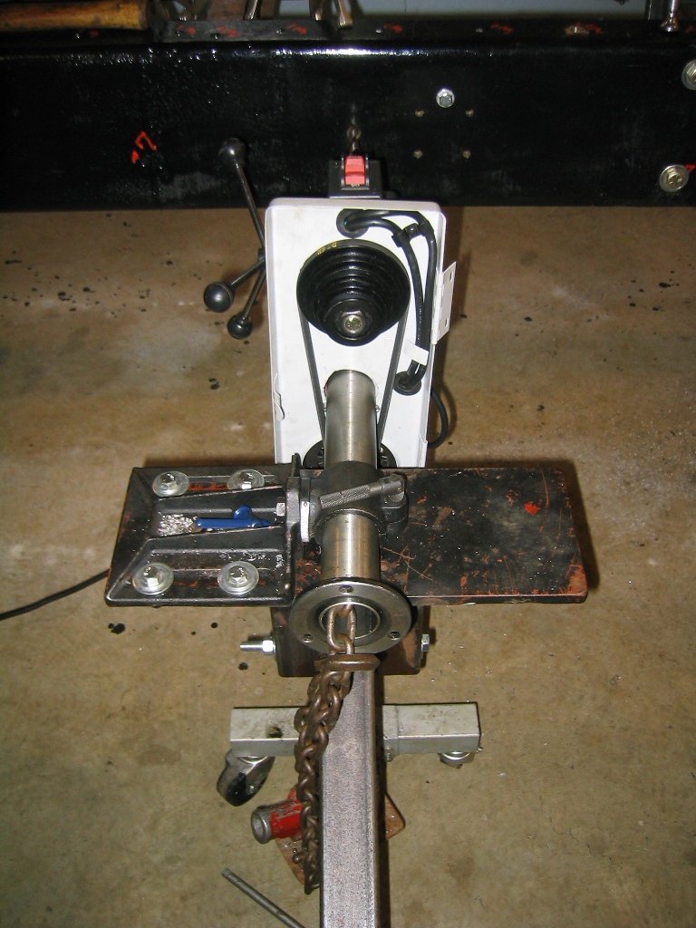
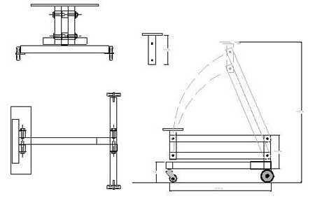
This drawing shows the layout of a adaptation of an engine stand to allow for parallel lifting. The layout of the arms which are made of 2x2" steel tubing keep the 1/2" thick steel lift plate parallel to the ground. A short section of 21/4x 21/4 " steel tubing which slides over the engine stand base and replaces the vertical part of the stand. When I needed to drill some 200 holes through the new inner frame rails to replace the rivets and wanted to insure a tight fit of the grade 8 bolts I looked at a magnetic based drill and found that they cost between $300 and $400. Instead modification to a $65 bench drill press allows it to drill vertically (up or down) or horizontally This rig allowed drilling 200+ holes ranging from 7/16" to 1/2" holes easily. Align the drill bit with the existing hole in the outer frame and drill through the 1/4" plate of the new inner frame. All holes were drilled to be a drive fit of the grade 8 bolts used to replace the rivets.
|
 |
 |
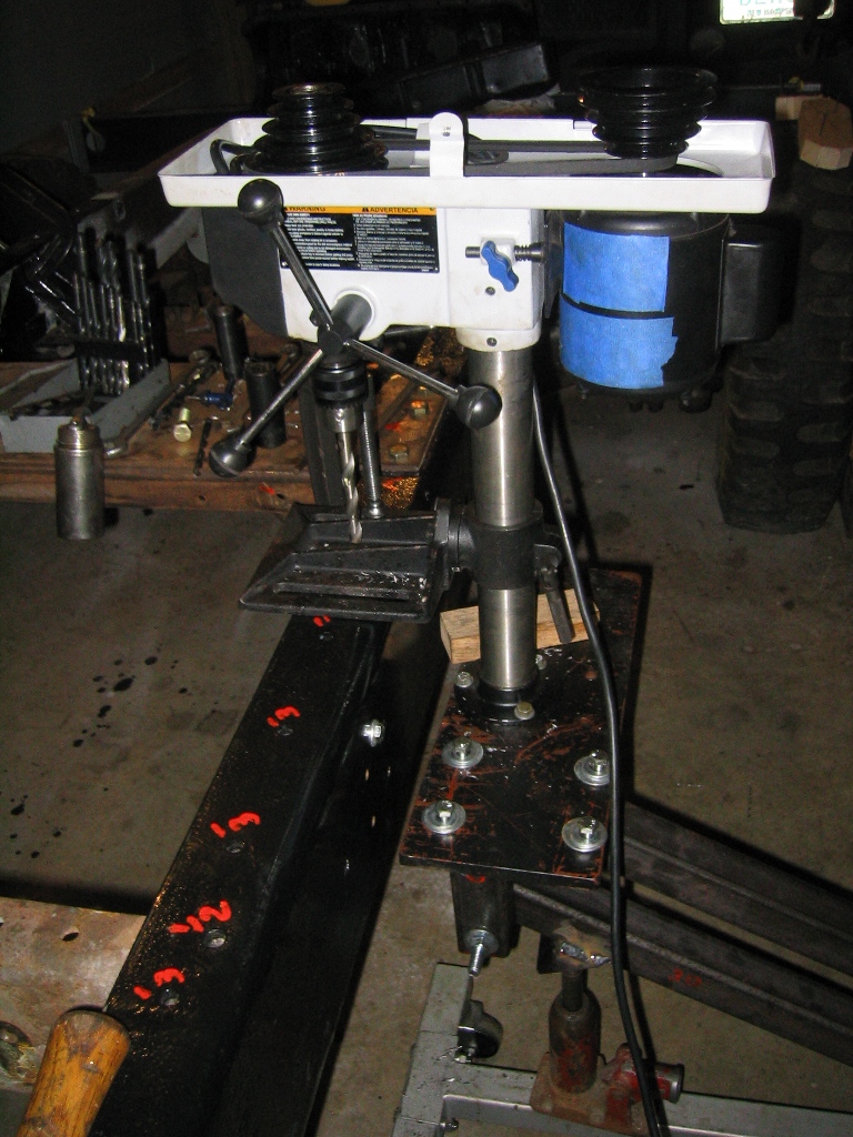
For vertical drilling down the drill plate is simply clamped to the frame with C-clamp or vise grip. |
For horizontal drilling press is bolted to the stand with a chain run through the drill post to hold the drill from rolling back. A simple simply hook the chain on the frame take up the slack at the base a chain hook provides for the adjustment.
|
|
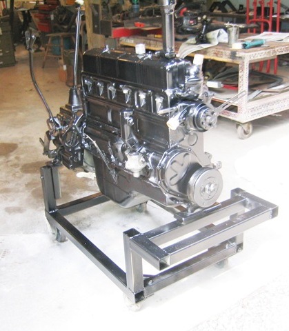
One of the more indispensable tool that I've made specifically for CMPs is and engine stand on wheels. See Engine Testing page for more information. Additional Information 2011, I now have four of these test stand as it makes it so much easier to store and work on engines. I have used wooden cradles but have found that these are vastly superior One important thing I have learned is DO NOT USE rubber or composite wheels no mater what they say they take a set and end up flat spotting which makes it hard to get a stand has been sitting for any length of time are. Metal wheels work much better Particularly on smooth floors. Link to Test Stand Design Page Drawing and Detail Photos |
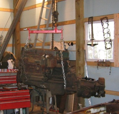
Lifting the Chevy engine out of a CMP is a problem, the cheepy engine leveling bars (below left) are really not worth buying between being cheeply made they are just to short to really pick up and balance a Stovebolt 6. Solution make up one that is long enough and heavy enough in design and build to handle the whole engine assembly. You can see a time lapse video of pulling engine out of C60S in 2009 Beauty Engine Pull HIRes.wmv (sorry this is a large file and may not work with a dial up connection. For more on pulling the engine and solving the problems of pull an engine out of a Pattern 13 CMP see HUP OVERHAUL
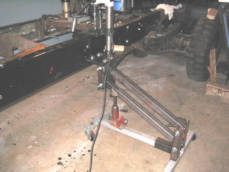
Many parts on CMPs are ackword to handel with uneven or off center Center of Gravity, the engine leveling bar particularly one that is able to handle a 1000 lbs+. The picture below shows the engine leveling bar being used to lift the rear axle assembly. |
|
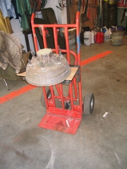
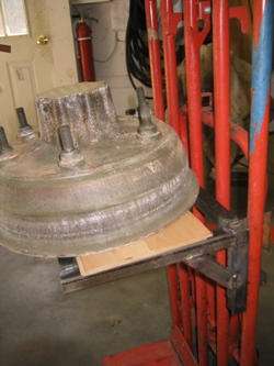
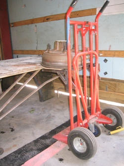
Pictures below show my most recent tool adaptation, faced with moving heavy parts around the shop to work on them such as brake drums and cylinder heads. My problem was picking them up off the floor, use the jib boom and chain fall or the platform lift solve that problem. But how to move them to painting table etc. the solution was to add a platform hand cart. Made of 1x1 tubing it hooks on to the hand cart. A little care is need obviously to not get over the center gravity. Also missing in these photos is a strap I generally use to be sure that the part doesn't slip off the platform while moving.
|
 |
| BACK TO HOME PAGE | |
 Repair Stand J-1716
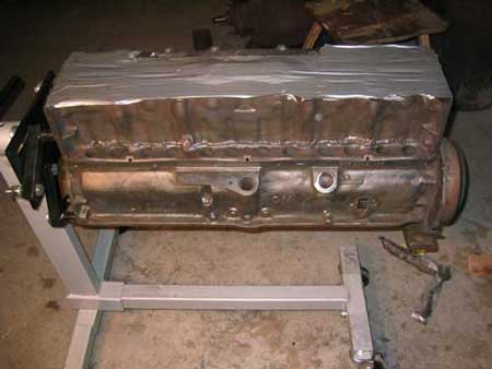
