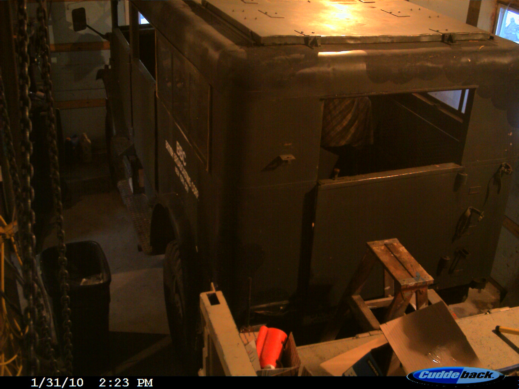
Though I built my shop with three CMPs in mind space is a little tight so planning and organization is needed to make the work easier. Also given the weight of various of the HUPs parts planning to be able to use the JIB Crane in the shop to do the heavy lifting is also part of the plan as is part storage access and organization. (Note the date on the time lapse camera was off for the first day should read 12/31/10)
Click on the photo at below for High Quality time lapse Video large file - best quality
Once the video is running remember to right click to select size of image.
 7MB Covering work 12/31/10 to 1/22/11 UP DATED
 7MB
Covering work 1/22/10 to 1/28/11 new 1/30/11
7MB
Covering work 1/22/10 to 1/28/11 new 1/30/11
Click on the photo at below for Smaller size image time lapse Video large file - for slower connection speeds
2MB Covering work 12/31/10 to 1/12/11 UP DATED
2MB Covering work 1/22/10 to 1/28/11 new 1/30/11
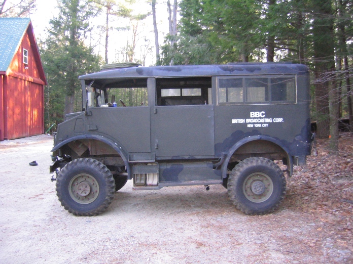
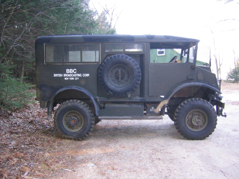
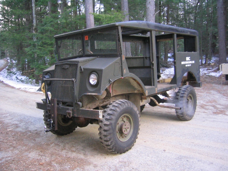
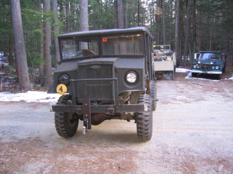
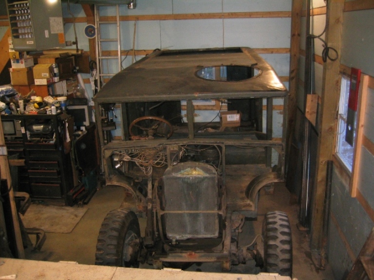
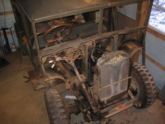
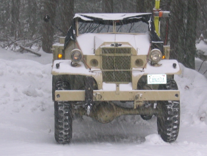
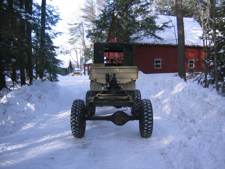
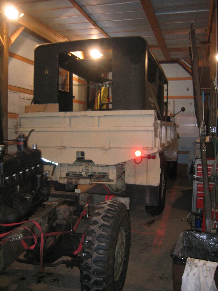
HUP 12-11-10 The condition that I drove it into the shop to start working on it.
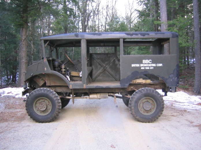
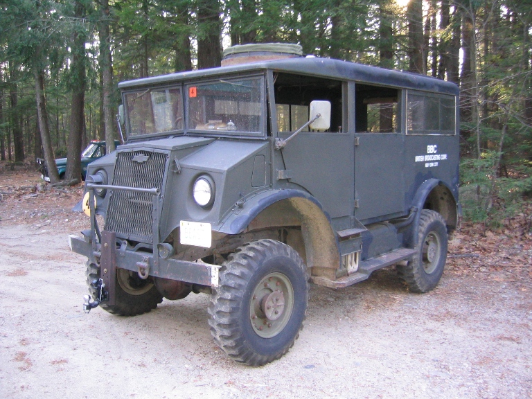
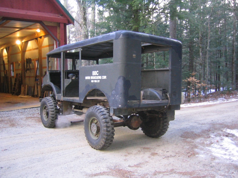
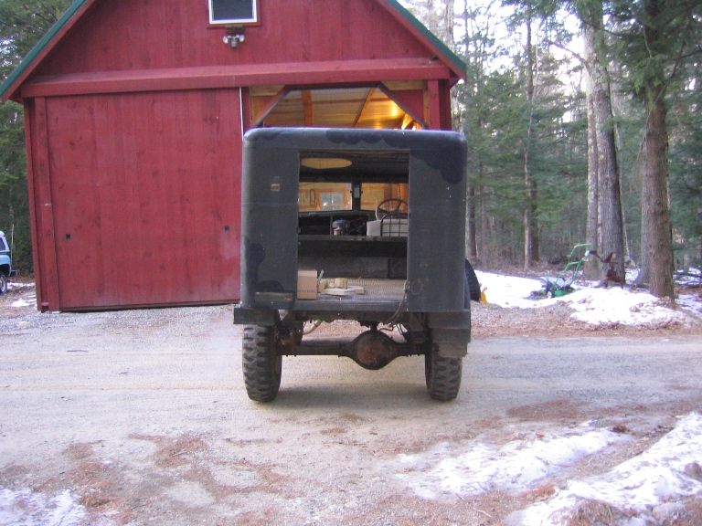
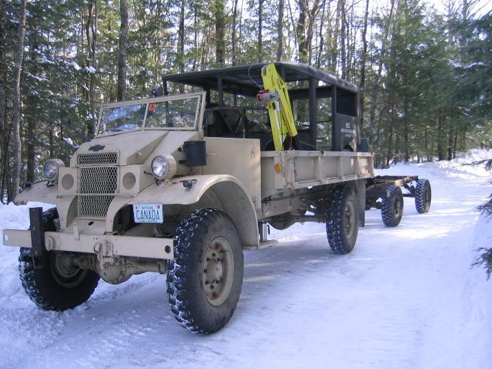
After taking time for family Christmas I started work on 12-31-2011. The picture above was taken on 1-5-11 when I backed the HUP out to turn it around to start disassembling the other side.
Updated and Information Added December 25, 2011
Information added Dec 25, 2011 its been about a year since I was at this point in the overhaul but this morning I got an e-mail from Pieter (another HUP restorer)
Hello Phil,
I need a little help on removing the front (nose) of the HUP.
I removed all nuts and bolts that I could find but still she won’t
come loose.
Is there a special sequence to remove the nose and are the some hidden bolts on the inside??
So decided to expand this section a little, because taking the nose of a HUP or and Pattern 13 CMP is easy once you find all the bolts and little connections that need to be removed.
Once you have done it a few times, it takes me about 3 hours working
time now from removing the first bolt to the nose sitting on the floor.
Given all the bolts unscrew with out breaking and you don't forget anything.
Getting all the connections in the right order was one of the reasons
I took time laps photos of removing the nose from my C60S helps in rigging
the lift and remembering what needs to be disconnected. Link
to Video makes it look easy Time
lapse more realistic.
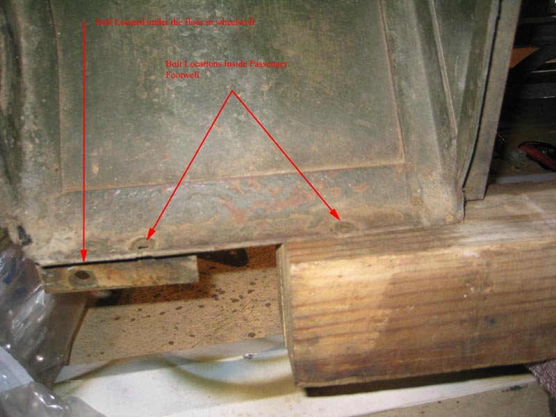
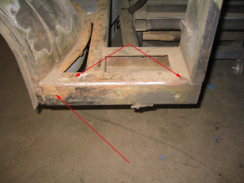
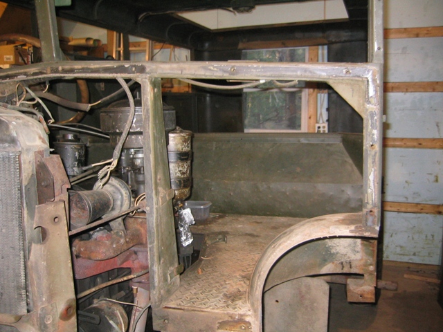
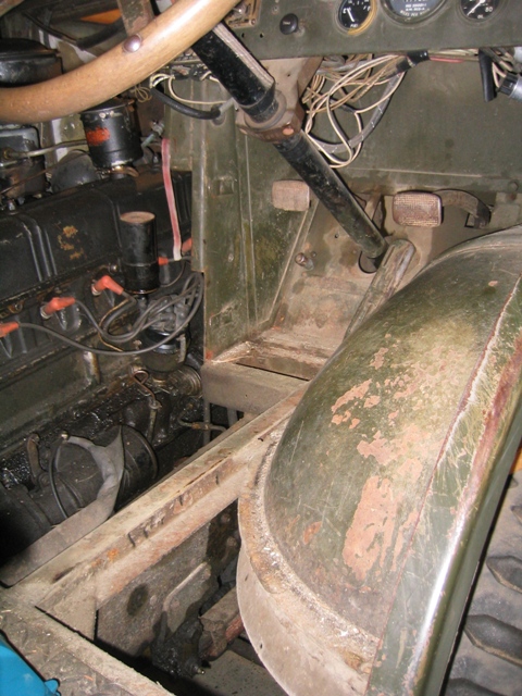
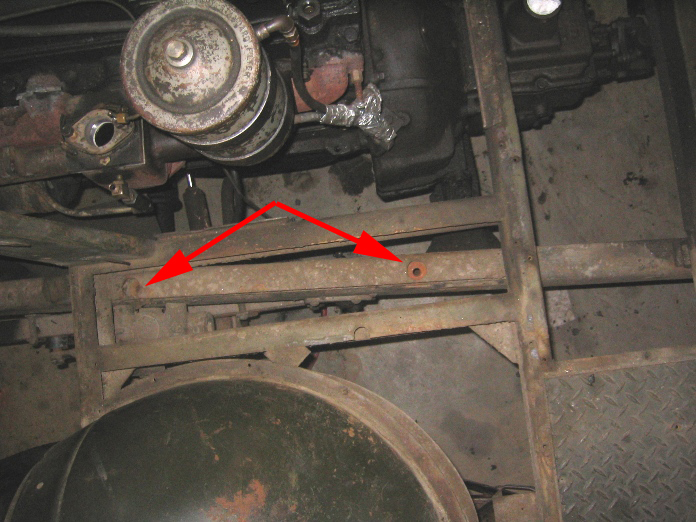
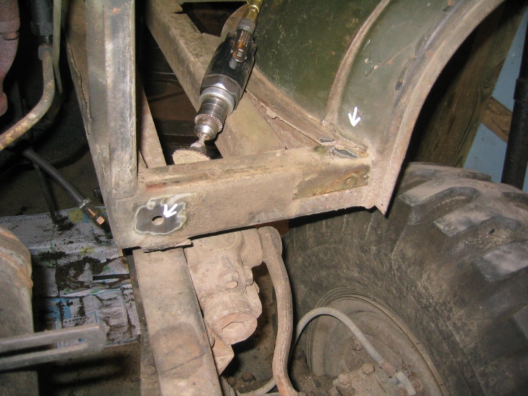
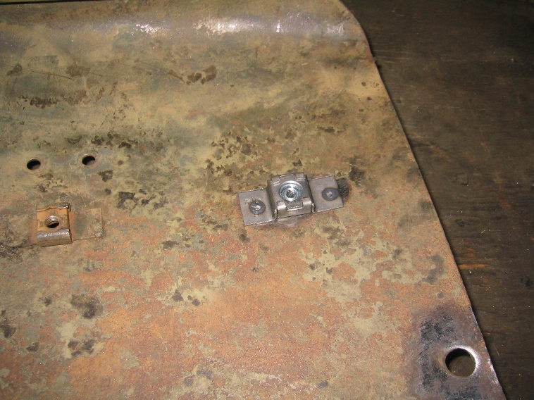
Above is the passenger side nose foot well looking forward there are two machine screw bolts which go down. There is also one bolt under the floor reached from the wheelwell.
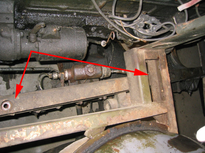
Below is the driver side looking from the front back in. Again there are the two bolts in the floor panels going down and the one bolt in the wheelwell.
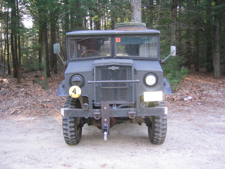
Steps in removing the nose from Pattern 13 Cab these are sort of a composite of doing this several times. Before you start make sure that your lifting hoist will be able to lift the nose straight up until the bottom clears the top of the radiator.
1. Disconnect and remove the marker lights
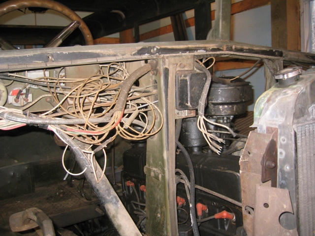
2. Disconnect the Headlight wiring harness both sides of the engine compartment under hood.
3. Disconnect or remove the horn wire to the steering column
4. Disconnect and slide coolant recovery rubber hose from radiator connection
5. Remove Throttle linkage that comes through the floor from the peddle
6. Remove the forward floor panel under brake and clutch peddles.
7. Remove the short front fender sections and the inner splash shields on side of radiator.
8. Remove front brush guard or remove entire bumper by unbolting the two tow ring assemble remember to support this assembly when removing the bolts.(see time-lapse) for hoist pickup
9. Remove the center nose bolt and spring under center of grill.
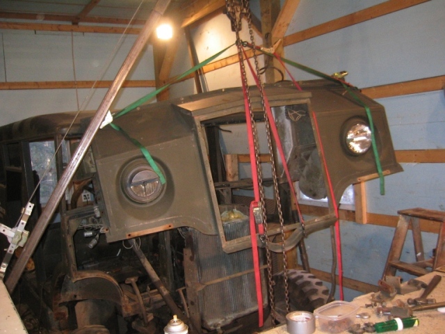
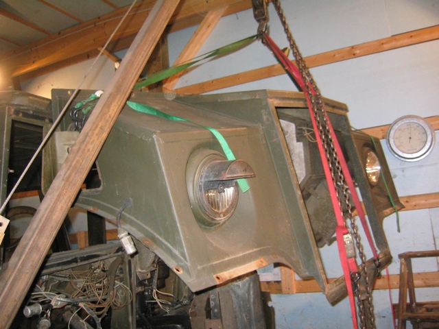
10. Rig nose for lifting I use ratchet cargo straps hook two through your lift hook down to the nose side vent doors, cushion straps and hooks with rags if you are concerned about scratches. Then run a third cargo strap down to the front so that you can get a good balance front and back. Take a slight load on your lift hook.
11. At this point you must decide what your are going to do about brake and clutch peddles. Choices remove completely, disconnect the linkages and let them swing forward and down clear of the nose.
12. Remove the nose bolts on the sides and across under the windscreen.
13. Take a little more strain on your lift hook. The nose has a rubber strip between the nose and the body which with age and paint may be holding the nose from moving, carefully pry the edge apart.
14. Nose assembly is meant to come forward about 2 inches then go straight up until it clears the top of the radiator. (Be very careful of the radiator)
15. If you get the nose to this point and it will move a little but doesn't want to come free you probably missed one or more bolts. If it moves up several inches then stops you've probably missed a wire or hose.
16. Other things that hang up shroud between the grill and radiator, some come out with removing, some are welded in place. The radiator cross bar can hang up.
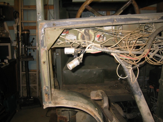
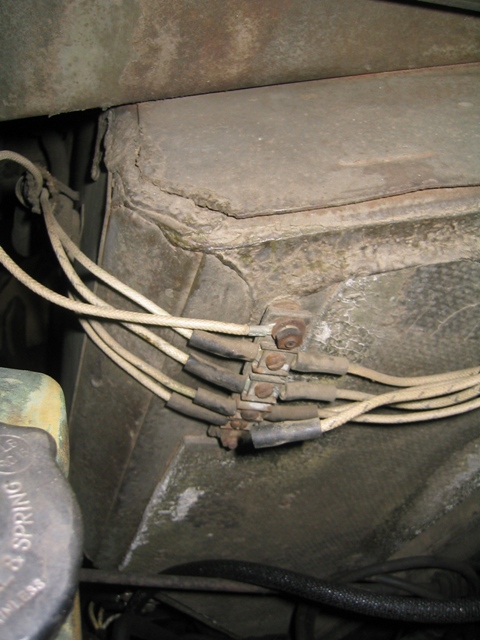
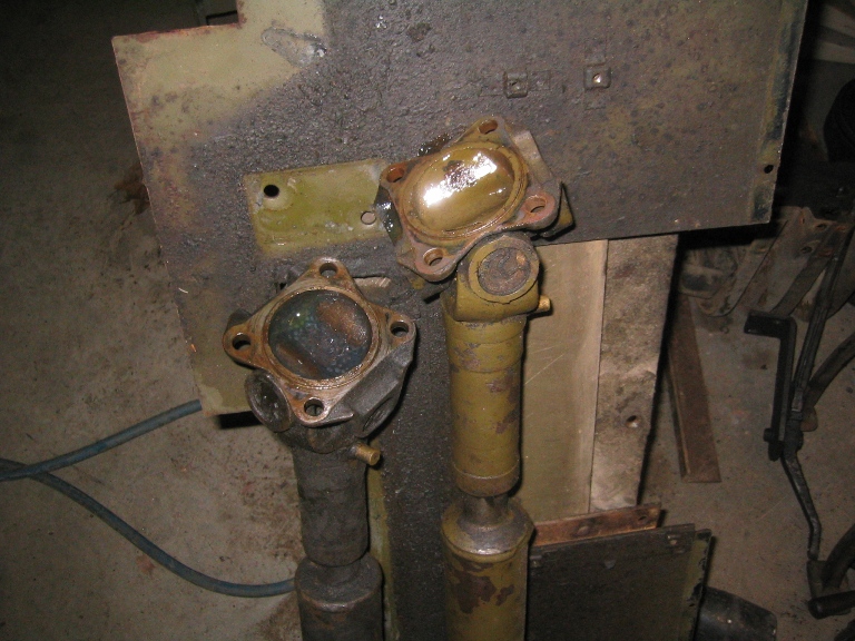
Drivers side headlight connection
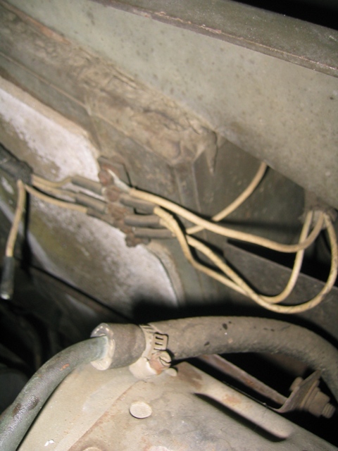
Passenger side headlight connection and radiator overflow/recovery line.
If your truck is equipped with a foot dimmer this must also be disconnected before forward floor is removed along with the weather seals if so equipped
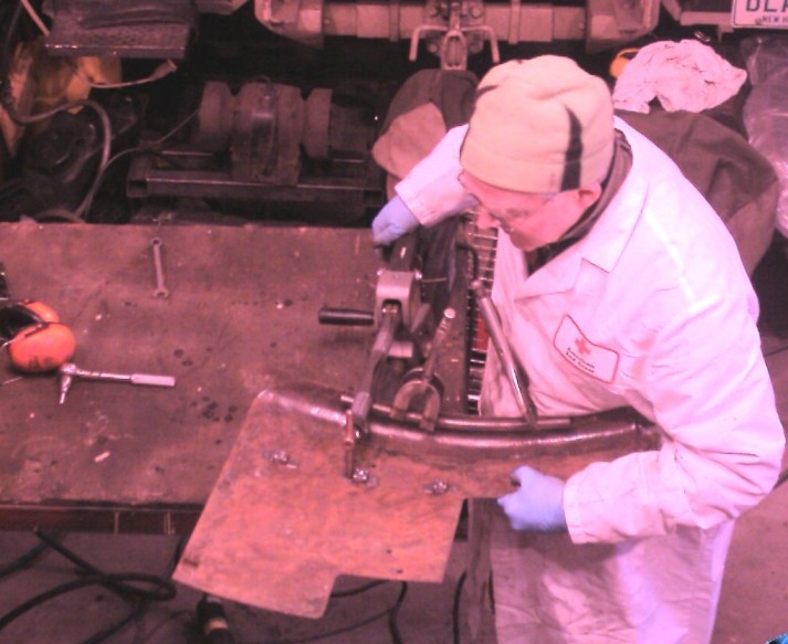
The photos above show steps of the progress of work, but they are just a few of the many documentation photos taken 175+/- so far.
Documentation photos are important to keep track of how things were assembled, saving time on reassemble. Another important function of photos taken is to document any problem areas, parts that will need repair. Each evening the photos are reviewed and notes made in a data base which list all special repairs that are needed (it also is a running tally on how much time is going into the project). Also in this data base are going notes on interesting discoveries along with notes on little tricks that have come from restoring three CMPs.
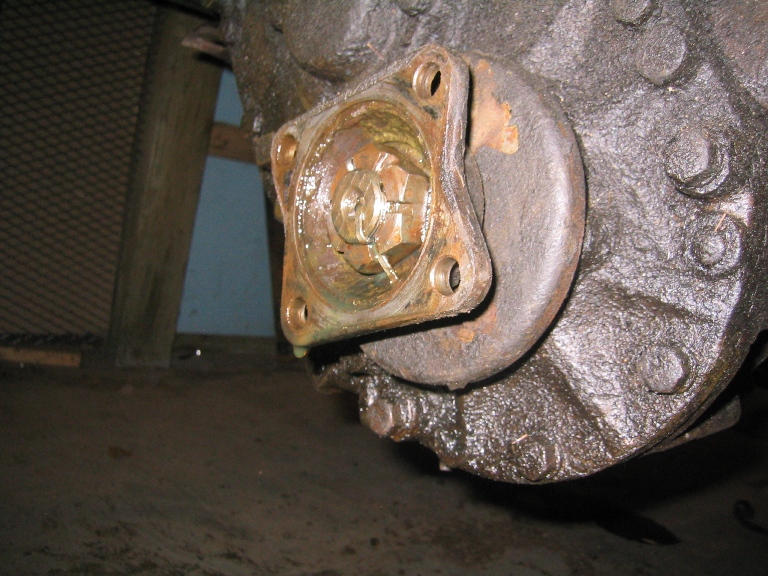
While as can be seen in the photo above of the rear of the transfer case oil leakage is a general issue. But what really needs to be noted is that the space between the flanges of the drive shaft and transfer case were filled with gear oil but not leaking out. The gear oil/lub is leaking along the splines of drive shaft. Made a note to put a little sealant on these flanges when reassembling to not having the flanges leak after reassembly.

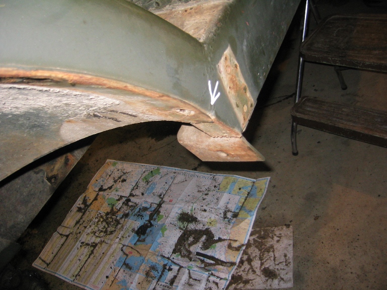
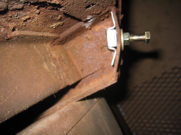
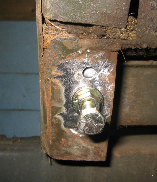
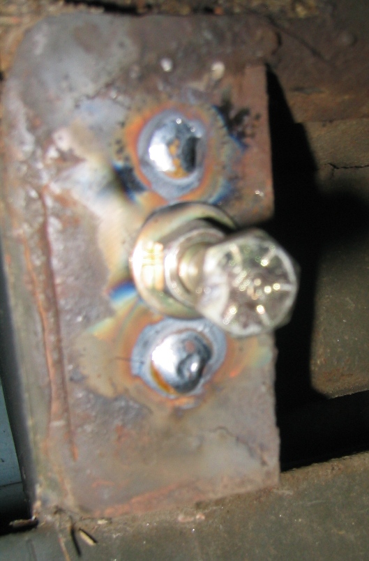
Picture above and at right show the front edge of the body frame which is showing a fatigue failure, this is a crack that has been evident for years but is in a location that could not actually be addressed with the body bolted to the frame.
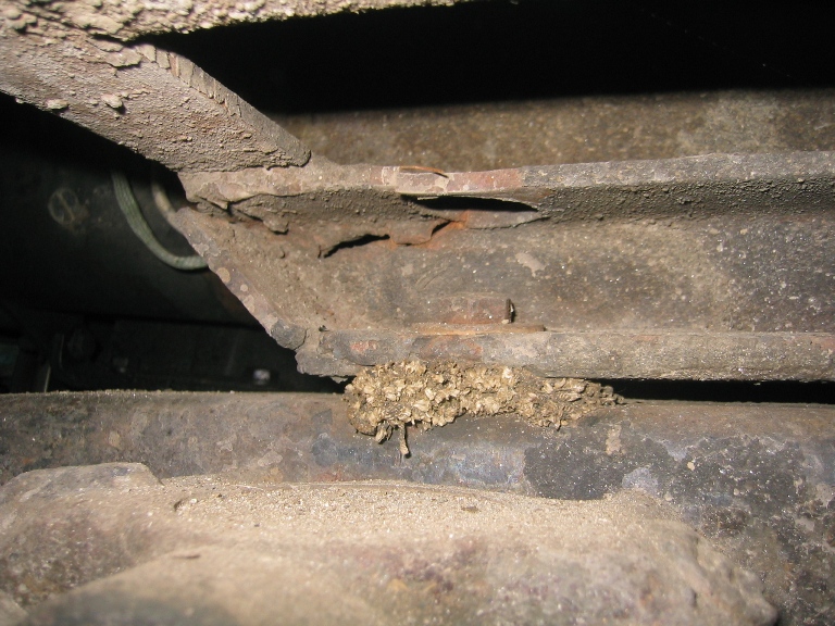
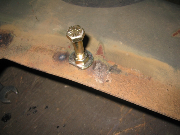
This crack also shows the location of one of the four bolts that hold the HUP body in place these are in addition to the U-bolts. They are hidden under the floor boards and require removing both front floor sections to access and remove. I was reminded to check for these by R. Clark aka Mr. HUP on the MLU forum http://www.mapleleafup.net/forums/showthread.php?t=15965 posting #8 . The pictures below show the location of these bolts. It is really hard, read impossible to lift the body off the chassis without removing these bolts. Make a note to put them back in before installing the floor plates.

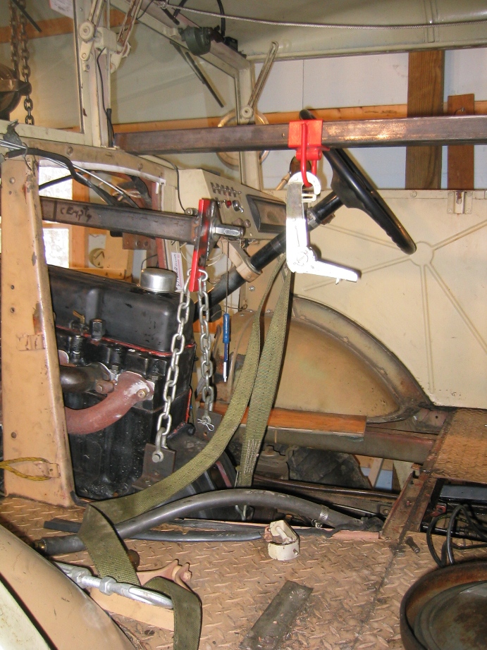
Photos like this one show things that are often lost in the process of cleaning parts. Above is the bracket that supports the steering box note the shims on the stud and threaded bolt hole. These are used to align the steering box.
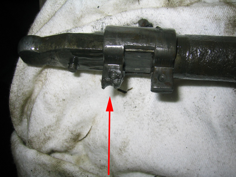
This photo shows the bottom of the shift lever and in particular the reverse lockout. What has to be determined the cause of the grove worn in the bottom lock out
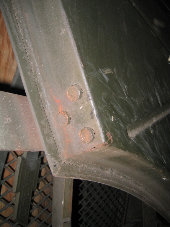
This a common place on the doors of Pattern 13 CMPs fatigue cracks at the hinge edge this one will take some thinking to figure out the best way of repairing cracks and reinforcing the area. Shown here is the bottom hinge of the drivers door.
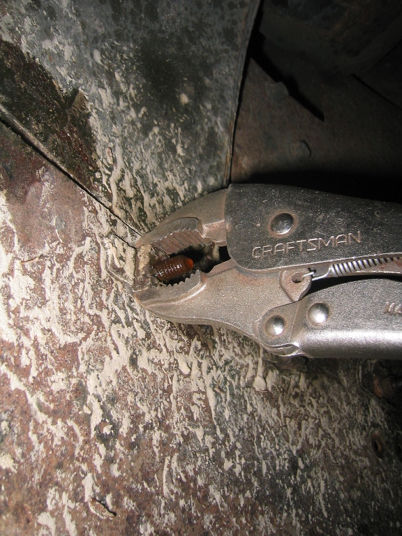
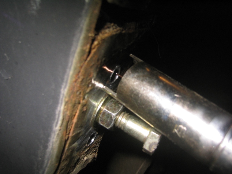
Tech tip CMPs made use a lot of caged nuts to speed assembly (just on modern vehicles) the ones on CMPs are surprising in that they can often be unscrewed without braking the bolts. First spray as many of these little critters with a good rust penetrating liquid, like WD 40 or any of the old line penetrating oils. I'm using a home brew suggested on the MLU forum, a 50/50 mix of acetone and automatic transmission fluid. Yes it actually does seem to penetrate faster and deeper than the commercial products.
Second if you can gently clamp the ear taps of the cage to the nut it keeps them from bending out and the nut spinning. Then use an impact wrench to spin the bolt. My results have been that most of the bolts spin out, a few brake.
UPDATED JANUARY 30, 2011
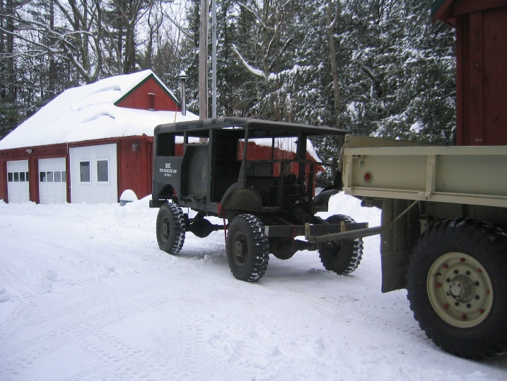
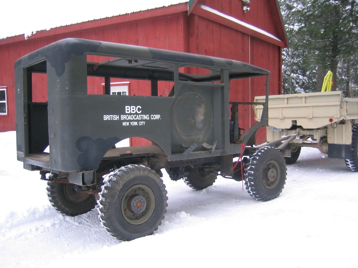
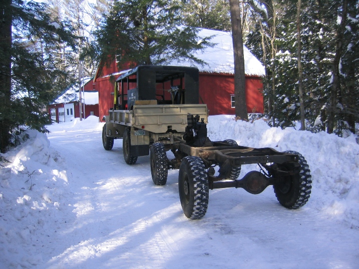
Lifting on the body off the frame has been on hold because of a series of snow storms, no snow to 28"inches in two weeks.
Everything that can be unbolted from the body has been removed the body is held on by 4 of the eyebolts. While waiting to remove the body and get to work on the frame and drive train, I've started working on cleaning parts and sheet metal
In the picture above right is shown one of the many caged nuts or captive nuts used on then body for the fenders, floor boards of the many used about a dozen either broke or spun the nuts. Because one of the primarily reasons for using them is that the nuts can not be seen, when the bolt brakes I mark the location for attention later.
The 1st step in replacing caged nuts is to remove the old cage, and air chisel is the best tool for this, if the bolt breaks the entire cage and nut can be removed with a pointed drift. Then preparing the area for the welding comes next. Air grinder with a scotch pad works well.
The best method of positioning the nut cages that I've found is bolt nut and washers, as shown in the two pictures below. Using a nut and bolt instead of a bolt and washer is that it is a lot quicker to hold the end of the bolt than trying to grab the head of a bolt that has been screwed down flush.
I use a pinch spot welder which is quick easy and is how the caged nuts were installed originally. Being sure to clean both sides of the body panel is critical to getting a good weld.
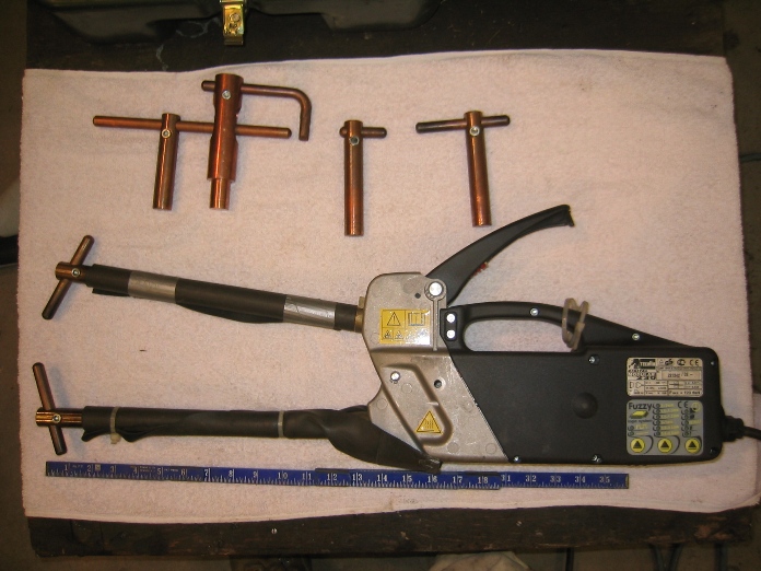
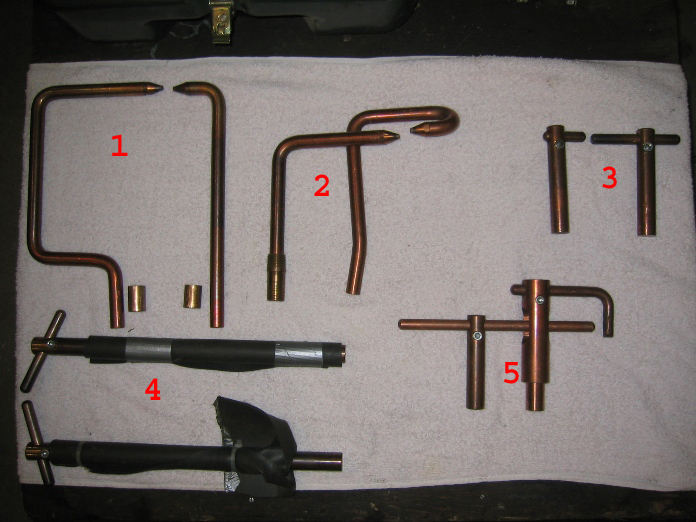
This is the spot welder and the special tips that I've bought over the years- 1. For reaching around obstacles, not used often on CMPs. 2 For inner and outer fender lips, not used often on CMPs 3 & 4 are the tips and arm most used the rubber sleeves on the long arms is to prevent accidental contact/grounding on the parts being welded. 5 is another lip welding tip.
Even with all these different tips there are places where you can get the tips in to pinch weld like the location at LEFT.
The solution is a plug weld, which requires drilling a 1/4" hole as show at left then with a mig welder centering on the hole and welding out to the surface as shown below and below left. This is of course is an option if you don't have a spot welder though it is a slower than a pinch welder. Its only real failing is that the welds are a little too good and if you have to replace the cage nut again in the future it is harder to break the weld and grind down the old weld.
Snowing again
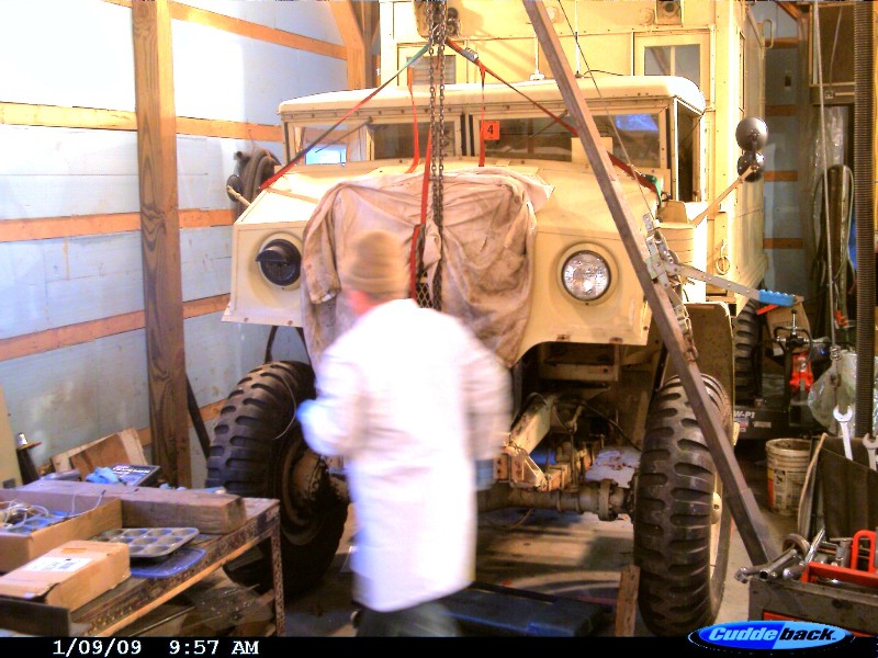
Getting the HUP ready to tow meant had to move the C60L out into the snow for the day.
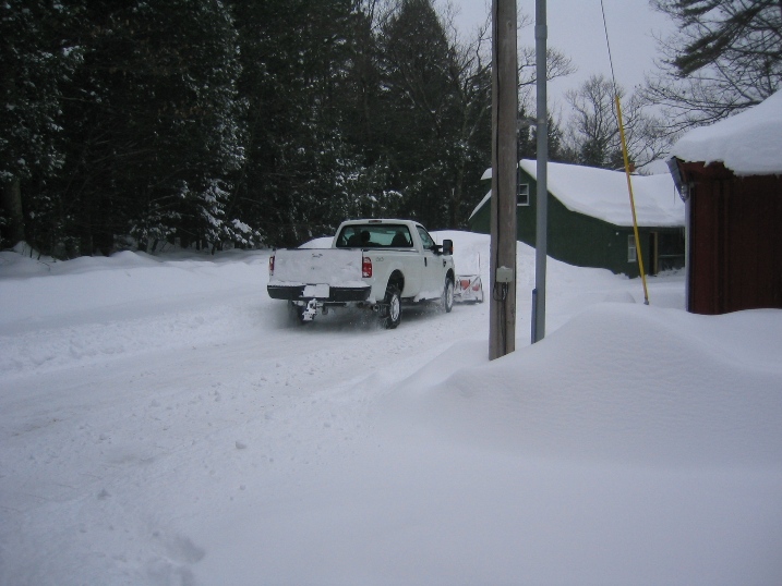
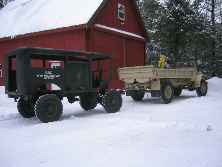
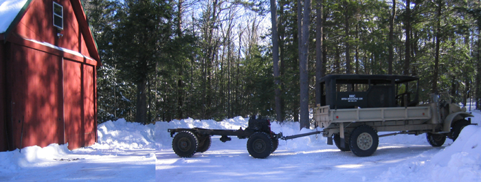
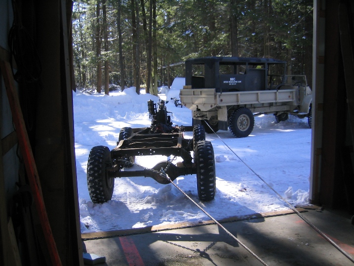
One of the bigger problems in the whole body lift operation was getting the HUP in and out of the shop. Unfortunately the barn is laid out so that a Y turn is required to pull into or out of the doors. This makes it easy to plow the doors but means turning the trucks.
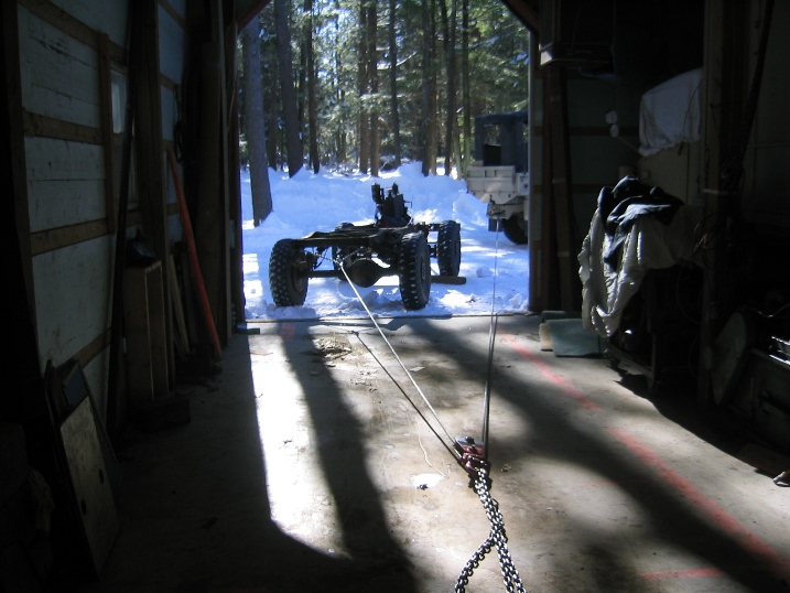
Solution to moving vehicles in and out of the shop that are not running is a winch point set in the floor of the shop. With the winch on the C60L this makes pulling things into the shop more of an issue of rigging than strength. Sill a slow process as because of the power of the winch means that you don't want to miss and hit anything or have the vehicle being pulled in run over the winch cable.
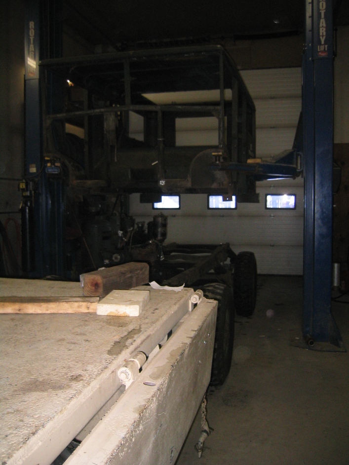
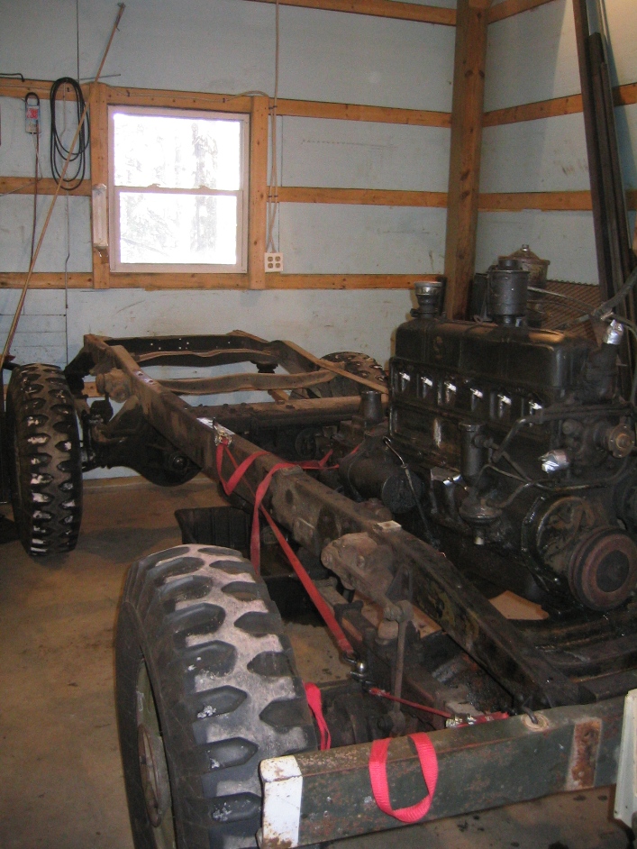
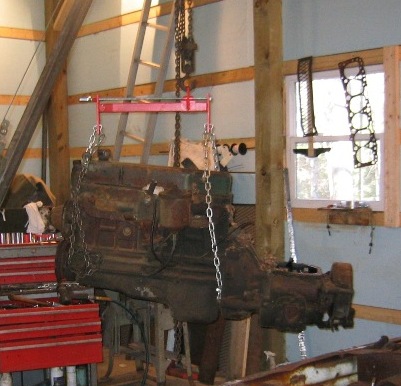
The pictures below, show that once the body was off removing the engine and transmission was very straight forward. The engine lift unit is one that I made up specifically for pulling engines out of CMPs (Beauty Engine Pull HIRes.wmv and Beauty Engine Install Hi Res.wmv on CMP Videos page)
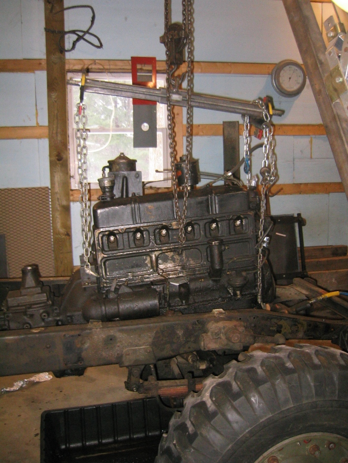
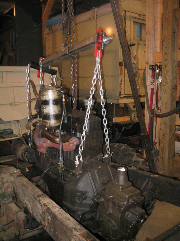
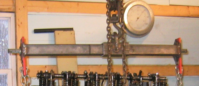
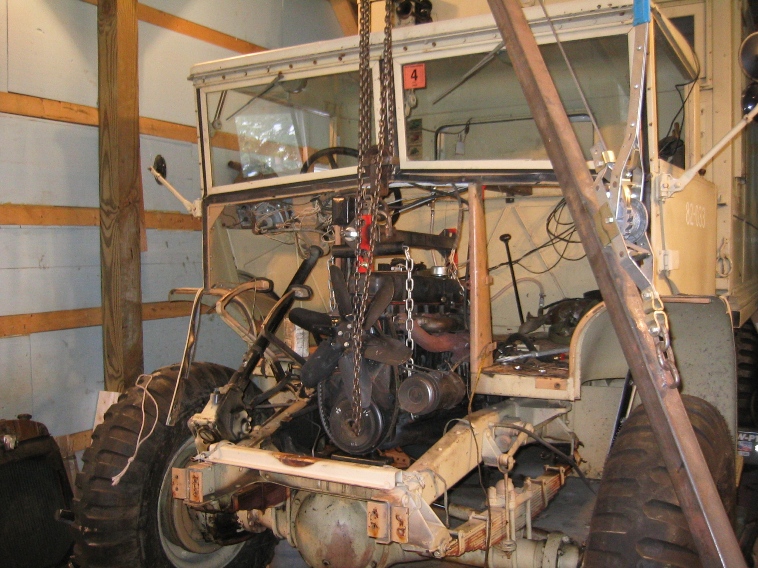
The Picture below shows a CHEEP Chinese engine leveling bar as found in many auto parts stores and online catalogs it is not worth anything, the screw drive is too weak (stripped the threads) the bar is too short. Solution cut it in half and use the two end plates with box tubing and a heavy threaded shaft. The result and engine bar that is the correct length for a Stovebolt 6 anything from the 216 to a 261 cubic inch with or without the transmission. Picture with cheep bar is 235 and the new bar is 261. Picture next frame down shows it being used to pull the engine out of Pattern 13 with cab in place
.
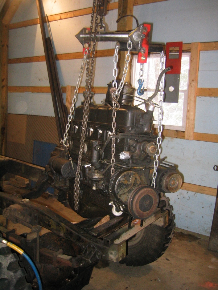
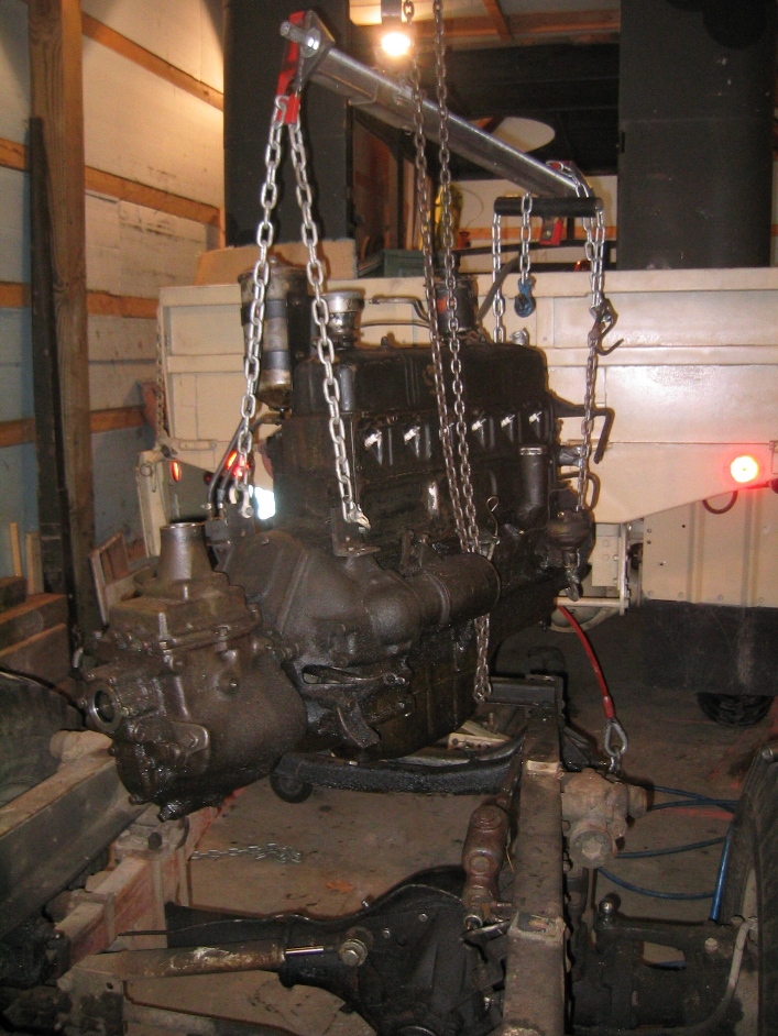
Engine Pickup Points
Over the years I have been improving my methods of lifting the engines out of CMPs following are some tips:
-
Don't lift the engine by the manifolds or head bolt locations- either of these locations is liable to cause leaks.
-
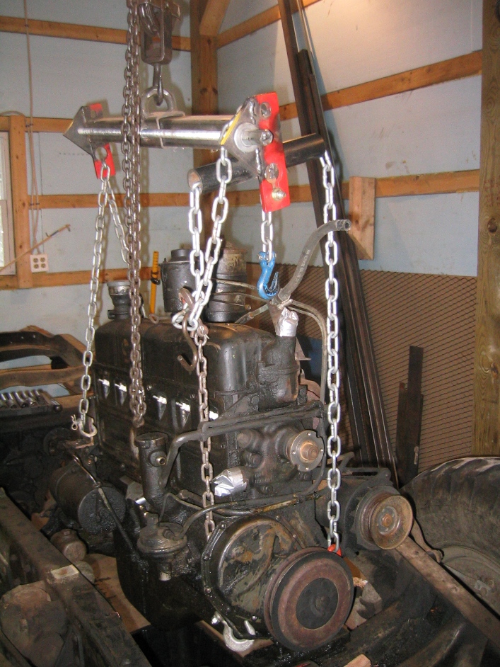
I added a load spreader pipe to my engine balance bar so that the chains on the front can go straight down and hook on to the lower engine mount.
-
Best rear engine point I've found is to use the four threaded bolt holes at the rear of the engine on the bell housing, attaching to these is simple with two pieces of angle iron.
-
The four point pickup gives a nice stable engine lift.
-
Because the cab design prevents putting the leveling bar in the center of gravity of the engine or engine and transmission as a unit means that the rear of the engine must be supported while the engine is lifted and moved forward. This can be accomplished with a slide rail in this case made from another length of box tubing which runs from the base of windshield to the rear lip of cab. In this case a part of the cheep leveling bar was used as a slide.
-
Note also that the leaving bar is marked showing the Center Empty and Center Level with Engine and Without. The slide can be driven back and forth under load with socket and impact wrench.
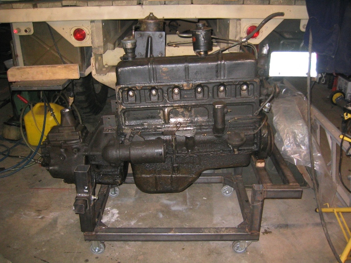
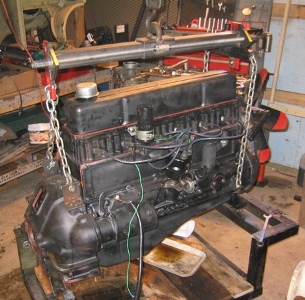
Engine Test Stand
The engine stands I use (now have three) deserves some explanation which I will have to add to the Restoration Tools and Tricks page you can see a good bit of how I've used them on the Engine Testing and Set Up page and on the CMP Video page.
In short though it is made up of 2x2 box tubing with a couple of 2 1/2 x 2 1/2 and 1 3/4 x 1 3/4 to provide slip joints. Makes moving the engine around lot easier.
| Go To HUP OVERHAUL 2011- Page 1 | Go To HUP OVERHAUL 2011- Page 2 |
| April Work - Page 3 was centered around the Transmission, Spring Shackles, Cleaning and Painting of the bottom of the body, Engine Testing then disassembly. | May Work - Page 4 included finding a replacement cylinder head, finding and installing spring shackle bushings and pins. Cleaning and painting the frame, |
| June Work - Page 5 painting and body work begins and trying to match the original color of the HUP, brake work, reassembly of the axle assembly. | July Work - Page 6 handling painting and body how do you pick up and turn a HUP body on its side by yourself. Machining the hardened steel spring shackles. Pictures of the wooden blocks used as frame inserts at the attachment locations. Brake line installation |
| August & September Work - Page 7 engine comes back from the machine shop almost ready for reassembly before the problems start. Body lowered on to the body for fitting and further body work, which included replacing some rusted damaged areas. | October & November Work - Page 8 body work continues, repairing the fatigue cracks in the front door where the hinges attach, a common CMP problem, installation of chassis parts like shocks. Problems with assembly of the engine but in the end everything is fitted in place. |
| December Work - Page 9 engine assembly completed and run in started on the test stand. Hidden design surprises in the CMP adaptation of the Stovebolt 6. Work on the chassis nearing completion with only a little painting and the installation of the wiring harness to be done. Body is ready to be primed and painted. | |
| BACK TO HOME PAGE | |